
User's Manual Part 1

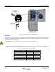


OS-1933-E3-003 Installation Instructions
2-6 044-05243 Rev A
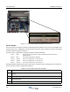
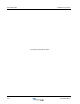
Figure 2-4 Form-C Alarms and External Alarms Connections
Form-C Alarms
The Form-C alarm connections are made at the terminal block located at the rear of the Control Module. The
contacts accept a 28 - 16 AWG wire. The alarm cable connection is shown in Figure 2-4 and the alarm wiring
and relay conditions are listed in Table 2-7.
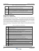
The minor, major, critical/bypass, and intrusion alarms are defined as follows:
All installed rectifier faulted would result in a loss of power. All Form-C alarms would default to the alarm state.
Connect the Form-C alarms as instructed in Table 2-7.
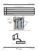
Alarm 1 Minor Any cabinet fan fault, intrusion, or rectifier communication fault. The system
requires attention.
Alarm 2 Major The system performance is degraded.
Alarm 3 Critical 1 Sector 1 is in bypass due to a Tx or Rx fault
Alarm 4 Critical 2 Sector 2 is in bypass due to a Tx or Rx fault
Alarm 5 Critical 3 Sector 3is in bypass due to a Tx or Rx fault
Table 2-7 Form-C Alarms Connection Procedure
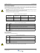
Step Action
1 To install the appropriate wiring and ease the wiring installation, disconnect the terminal block from the
booster.
2 Strip wiring insulation approximately 7 mm (0.3 in).
3 Use a slotted screwdriver with a maximum width of 0.100 inches to back out terminal screws enough to
allow wire insertion.
4 Insert stripped wire into terminal and tighten set screw a maximum of 2-inch pounds.