
User's Manual Part 1


OS-1933-E3-003 Installation Instructions
2-4 044-05243 Rev A
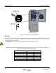
Figure 2-1 AC Power Connections Example
RF Cable
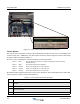
All cable connections are made at the system cabinet lower-rear RF interface bulkhead panel as listed in Table
2-6. Figure 2-2 shows the interface bulkhead ports. Verify the BTS output power does not exceed the
requirements detailed in Chapter 5.
CAUTION: Prior to connecting BTS cables, verify booster system power is off.
NOTE: Do not install weatherproofing materials to cables until the booster commissioning is completed.
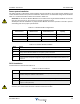
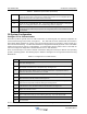
Table 2-6 OS System RF Cable Connections
Bulkhead Port Connector Connects between...
BTS TX1/RX BTS
OS System
BTS TX2/RX BTS OS System
TX3 BTS OS System
TX4 BTS OS System
ANT TX/RX OS System Antenna
ANT RX OS System Antenna
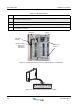
LGN
J1
0.5 to 0.625"
AC Power
Connections
Common Earth
Ground
Terminal
Spring Cage
Terminal Block