
User's Manual
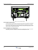
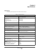
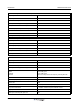
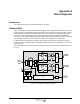
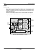
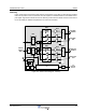


Table Of Contents
- Revision Record
- Table of Contents
- List of Figures
- List of Tables
- Abbreviations
- Chapter 1 Product Description
- Introduction
- Scope of Manual
- Safety
- Human Exposure of RF Radiation
- Sub Unit Overview
- Wideband Amplifier PCBA (WBA)
- Power Amplifier PCBA (PA)
- Multi-Carrier Power Amplifier PCBA (MCPA)
- Booster Amplifier PCBA (BA)
- Control Unit PCBA (CU)
- Distribution PCBA (DIA)
- Low Noise Amplifier (LNA)
- Duplex Filter (DPX)
- Fiber Optic Unit (FOU)
- Fiber Optic Node (FON)
- Power Supply Unit (PSU)
- Remote Control Unit (RCU)
- Alarm Interface PCBA (ALI) and Remote Control Interface PCBA (RCI)
- Sub Unit Locations
- Fiber Optic Distribution Networks
- Multi-Operator Configurations
- Chapter 2 Controls, Indicators and Connectors
- Chapter 3 Installation
- Chapter 4 Maintenance
- Chapter 5 Specifications
- Appendix A Block Diagrams

WRH-V Wideband Radio Head
A-2 044-05251 Rev A
WRH-V
Non-Diversity
Figure A-2 illustrates non-diversity block diagram configuration of the WRH-V. The WRH-V is always
fed by a BTS via either a BMU or an OCM. The TX signal from the BTS is converted to an optical
signal in a BMU or OCM and fed to the WRH-V via a fiber optic cable. The optical signal is received
by the FON and converted to an RF signal. The FON supervises the signaling and reports errors via
the RCU connected to the CU.
The RF signal enters the WBA, is amplified, and further amplified in amplifier stages followed by
controllable attenuators. The signal exits the WBA and enters the MCPA where it is amplified and fed
to the DPX. The amplified output signal passes the DPX before it is fed to the service antenna.
The uplink signal path is located on the same WBA but only has an LNA before entering the WBA.
Figure A-2 WRH-V Block Diagram - Non-Diversity
WDM
FOU
DX
DX
DPX
DPX
WBA
WBA
DL
DL
UL
UL
LNA
LNA
MCPA
MCPA
To/From
OCM or
BMU
RCU
RCI
PSU
CU
FON
ALI
To
External
alarms
850 MHz
TX0/RX0
1900 MHz
TX0/RX0