
User's Manual
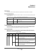
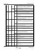
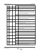
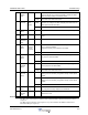
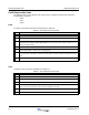
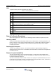
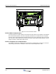
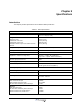
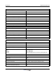
Table Of Contents
- Revision Record
- Table of Contents
- List of Figures
- List of Tables
- Abbreviations
- Chapter 1 Product Description
- Introduction
- Scope of Manual
- Safety
- Human Exposure of RF Radiation
- Sub Unit Overview
- Wideband Amplifier PCBA (WBA)
- Power Amplifier PCBA (PA)
- Multi-Carrier Power Amplifier PCBA (MCPA)
- Booster Amplifier PCBA (BA)
- Control Unit PCBA (CU)
- Distribution PCBA (DIA)
- Low Noise Amplifier (LNA)
- Duplex Filter (DPX)
- Fiber Optic Unit (FOU)
- Fiber Optic Node (FON)
- Power Supply Unit (PSU)
- Remote Control Unit (RCU)
- Alarm Interface PCBA (ALI) and Remote Control Interface PCBA (RCI)
- Sub Unit Locations
- Fiber Optic Distribution Networks
- Multi-Operator Configurations
- Chapter 2 Controls, Indicators and Connectors
- Chapter 3 Installation
- Chapter 4 Maintenance
- Chapter 5 Specifications
- Appendix A Block Diagrams

Field Replaceable Units Wideband Radio Head
4-6 044-05251 Rev A
Field Replaceable Units
The following units can be replaced in the field on-site by a qualified technician with experience
maintaining RF equipment:
• FON
• PSU
• WRH
FON
To replace a FON PCBA, proceed as described in the Table 4-3.
Table 4-3 FON Replacement Procedure
PSU
To replace a PSU, proceed as desribed in the Table 4-4.
Table 4-4 PSU Replacement Procedure
Step Action
1 Open WRH door and secure
2 Locate power connector on FON and remove connector from PCBA
3 Verify all cables on FON are labeled before disconnecting, then disconnect all cables. CAUTION: Do
not look into the end of any fiber optic cable. Be sure to cap fiber optic cables to protect the con-
necting end from damage.
4 Remove screws securing FON PCBA to FOU and remove PCBA
5 Replace FON PCBA in reverse order and apply power
6 Connect PC to OM Online port, login to FON and verify configuration and IP address. NOTE: Make
sure ‘Fiberoptical’ classmark in the FON Status window is checked, otherwise FON will not be opera-
tional.
7 Close WRH door and secure
Step Action
1 Open WRH door and secure
2 Disconnect main power plug from PSU
3 Disconnect power cable bundle from PSU
4 Loosen screws securing PSU using a 5mm Allen key and remove.
NOTE: screws are designed to not be removed completely from PSU.
5 Replace PSU in reverse order and apply power
6 Close WRH door and secure