
User's Manual
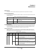
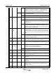
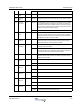
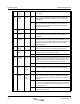
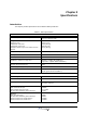
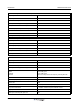
Table Of Contents
- Revision Record
- Table of Contents
- List of Figures
- List of Tables
- Abbreviations
- Chapter 1 Product Description
- Introduction
- Scope of Manual
- Safety
- Human Exposure of RF Radiation
- Sub Unit Overview
- Wideband Amplifier PCBA (WBA)
- Power Amplifier PCBA (PA)
- Multi-Carrier Power Amplifier PCBA (MCPA)
- Booster Amplifier PCBA (BA)
- Control Unit PCBA (CU)
- Distribution PCBA (DIA)
- Low Noise Amplifier (LNA)
- Duplex Filter (DPX)
- Fiber Optic Unit (FOU)
- Fiber Optic Node (FON)
- Power Supply Unit (PSU)
- Remote Control Unit (RCU)
- Alarm Interface PCBA (ALI) and Remote Control Interface PCBA (RCI)
- Sub Unit Locations
- Fiber Optic Distribution Networks
- Multi-Operator Configurations
- Chapter 2 Controls, Indicators and Connectors
- Chapter 3 Installation
- Chapter 4 Maintenance
- Chapter 5 Specifications
- Appendix A Block Diagrams

Wideband Radio Head Troubleshooting
044-05251 Rev A 4-5
Remarks:
The Door open alarm requires an optional door switch described in the P33 Alarm Port section in
Chapter 5.
The Main power breakdown alarm requires a relay not included in the WRH (see Main Power
Breakdown Relay in Chapter 3).
48 Battery
backup
fault
External Error If a battery backup unit alarm is connected to external alarm 2,
then the operator can configure the WRH to display this alarm
when the battery backup unit indicates alarm.
Ceasing The cause of the alarm has ceased.
50 Fiberopti-
cal error
FOT
fiber
optics
Config-
urable
If a fiber unit alarm is connected to external alarm 3, then the
operator can configure the WRH to display this alarm when the
fiber optical unit indicates alarm.
Ceasing The cause of the alarm has ceased.
70 Bad table
alarm
CU Error Requested table contains incorrect information (SW error).
71 Table not
found
CU Error Requested table not found in the database (SW or calibration
error).
72 Table
database
error
CU Error Table database not found (calibration error).
80 Antenna
SWR
alarm
Donor
antenna
service
antenna
Error Too low antenna return loss, caused either by cables, connec-
tors, or antenna problems.
Suggested remedy: Check antenna and cables.
Ceasing The cause of the alarm has ceased.
90 FON
power
alarm
FON RF Error A DC voltage on a FON PCBA is out of range. Suggested rem-
edy: Replace the FON PCBA.
Ceasing The cause of the alarm has ceased.
91 FON
TxStable
alarm
FON RF Error Laser transmitter control loop voltage out of range. Suggested
remedy: Replace the FON PCBA.
Ceasing The cause of the alarm has ceased.
92 FON
RxLevel
alarm
FON Warning Received optical level is below any of the two limits (one for
Warning and one for Error). Suggested remedy: Check optical
cables.
Error Received optical level is below any of the two limits (one for
Warning and one for Error). Suggested remedy: Check optical
cables.
Ceasing The cause of the alarm has ceased.
93 FON SPI
alarm
FON
F2F
Error The SPI bus connection to the RF modem does not work prop-
erly. Suggested remedy: Replace the FON PCBA.
245 Not In
Allowed
Area
CU None WRH is moved from the operating area and the RF HW is
switched on or off.