
User's Manual
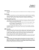
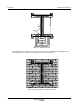
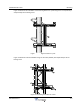
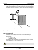

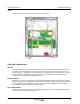
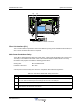
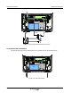
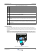
Table Of Contents
- Revision Record
- Table of Contents
- List of Figures
- List of Tables
- Abbreviations
- Chapter 1 Product Description
- Introduction
- Scope of Manual
- Safety
- Human Exposure of RF Radiation
- Sub Unit Overview
- Wideband Amplifier PCBA (WBA)
- Power Amplifier PCBA (PA)
- Multi-Carrier Power Amplifier PCBA (MCPA)
- Booster Amplifier PCBA (BA)
- Control Unit PCBA (CU)
- Distribution PCBA (DIA)
- Low Noise Amplifier (LNA)
- Duplex Filter (DPX)
- Fiber Optic Unit (FOU)
- Fiber Optic Node (FON)
- Power Supply Unit (PSU)
- Remote Control Unit (RCU)
- Alarm Interface PCBA (ALI) and Remote Control Interface PCBA (RCI)
- Sub Unit Locations
- Fiber Optic Distribution Networks
- Multi-Operator Configurations
- Chapter 2 Controls, Indicators and Connectors
- Chapter 3 Installation
- Chapter 4 Maintenance
- Chapter 5 Specifications
- Appendix A Block Diagrams

Wideband Radio Head Commissioning
044-05251 Rev A 3-9
Table 3-3 PSU Replacement Procedure
Commissioning
Before proceeding, carefully read the Safety section and check all connections made during the
installation. To fulfill the IP65 weather protective requirements, ensure cable strain relief bushings are
properly tightened. Also, ensure gaskets at cable inlets and on the cabinet are properly fitted and not
damaged.
A WRH can be configured locally with OM-Online by connecting a standard serial cable from the
COM port on the PC to the P31 PC port (RS-232) located to the right in the cabinet (see Figure 3-14).
The P31 PC port is described in Chapter 2. OM-Online is described in the OM-Online User Manual.
Figure 3-11 Connecting a PC for Local Access
Step Action
1 Disconnect main power
2 Remove the main power plug from the PSU ('1' in Figure 3-12)
3 Disconnect the power cable bundle connectors (2) on the PSU
4 Loosen the four fixing screws (3) using a 5mm Allen key and remove the PSU
6 Examine the removed PSU and identify the supply voltage for the WRH (13.5V or 27V)
7 Set the new PSU to the correct supply voltage by moving the jumper as illustrated on the PSU. This
must be done before the PSU is mounted in the WRH
8 Mount the PSU with the four fixing screws (3)
9 Connect the PSU to the DIA PCBA (2) with a cable marked VE007 98/1. This cable must be used
even if one connector will be left over at the DIA PCBA (previous versions of the DIA had only one
connector)
10 Connect the DC power cable. The supplied cable should have a radiation limiter. The + pole should
be connected to one of the left terminals in the PSU connector with the brown part of the DC cable.
The – pole should be connected to one of the right terminals in the PSU connector with the blue part
of the DC cable
11 Apply power and verify the yellow LED on the PSU lights
MS
DPX
ANT
TEST
DC
-30 dB
-20 dB
POWER SUPPLY UNIT
ALLGON INNOV ATION
SWEDEN M105 R6
1
PARKING
FOR W5
W5
8
P27
W6B 10
1
P33
ALARM
P23
LNA
UP-LINK
P32
MODEM
A
U
X
1
P28
DOOR
5
9
6
1
1
16
1
1
M
-
>
S
P11
P34
8
9
15
P26
15 16
S
-
>
M
1
2
3
89
P
3
6
5
X0A
X0B
2
V2
1
16
P12 P13
1
1
1
16
16
16
P4
P5
P6
c
b
a
c
b
a
c
b
a
c
b
a
1P232
1
b
a
1
16P3
16
1
16
P14
1
V1
1
1
1
1
1
4
6
1
15
6
9
15
2
16
1
2
4
5
8
5
P35
P21
PSU
6
10
P31
PC
P29
P24
P25
GND
7
6V6
LNA
DOWN-LINK
LED
P22
1
2
P31