
User's Manual
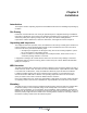
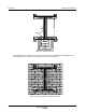
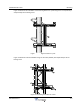
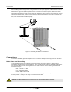

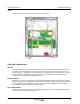
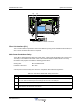
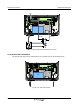
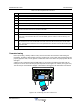
Table Of Contents
- Revision Record
- Table of Contents
- List of Figures
- List of Tables
- Abbreviations
- Chapter 1 Product Description
- Introduction
- Scope of Manual
- Safety
- Human Exposure of RF Radiation
- Sub Unit Overview
- Wideband Amplifier PCBA (WBA)
- Power Amplifier PCBA (PA)
- Multi-Carrier Power Amplifier PCBA (MCPA)
- Booster Amplifier PCBA (BA)
- Control Unit PCBA (CU)
- Distribution PCBA (DIA)
- Low Noise Amplifier (LNA)
- Duplex Filter (DPX)
- Fiber Optic Unit (FOU)
- Fiber Optic Node (FON)
- Power Supply Unit (PSU)
- Remote Control Unit (RCU)
- Alarm Interface PCBA (ALI) and Remote Control Interface PCBA (RCI)
- Sub Unit Locations
- Fiber Optic Distribution Networks
- Multi-Operator Configurations
- Chapter 2 Controls, Indicators and Connectors
- Chapter 3 Installation
- Chapter 4 Maintenance
- Chapter 5 Specifications
- Appendix A Block Diagrams

Wideband Radio Head Connections
044-05251 Rev A 3-5
Fiber Optic and RF Connections
Fiber optic and RF cable connections should be verified both internally and externally before
powering up the equipment. This section illustrates the general internal connections of the WRH and
WRH-V. Verify these connections with the as-built drawings and documents for your specific system
configuration. Table 3-1 lists the steps for external connections to the WRH.
Table 3-1 Cable Connection Procedure
WRH
Figure 3-6 illustrates the cables and connections for a standard WRH.
Figure 3-6 WRH Cable Connections
Step Action
1 Connect the service antenna coaxial cable to the left in the cabinet using an N-type male connector.
2 Connect the fiber optic cable from the OCM or BMU to the fiber optic cable demark on the FOU.
3 Connect station ground.
4 Mount the main power plug to the main power cord and connect it to the PSU.