
User's Manual
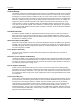
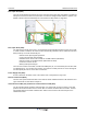
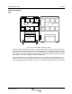
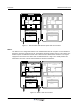
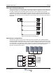

Table Of Contents
- Revision Record
- Table of Contents
- List of Figures
- List of Tables
- Abbreviations
- Chapter 1 Product Description
- Introduction
- Scope of Manual
- Safety
- Human Exposure of RF Radiation
- Sub Unit Overview
- Wideband Amplifier PCBA (WBA)
- Power Amplifier PCBA (PA)
- Multi-Carrier Power Amplifier PCBA (MCPA)
- Booster Amplifier PCBA (BA)
- Control Unit PCBA (CU)
- Distribution PCBA (DIA)
- Low Noise Amplifier (LNA)
- Duplex Filter (DPX)
- Fiber Optic Unit (FOU)
- Fiber Optic Node (FON)
- Power Supply Unit (PSU)
- Remote Control Unit (RCU)
- Alarm Interface PCBA (ALI) and Remote Control Interface PCBA (RCI)
- Sub Unit Locations
- Fiber Optic Distribution Networks
- Multi-Operator Configurations
- Chapter 2 Controls, Indicators and Connectors
- Chapter 3 Installation
- Chapter 4 Maintenance
- Chapter 5 Specifications
- Appendix A Block Diagrams

Wideband Radio Head Overview
044-05251 Rev A 1-7
Sub Unit Locations
WRH
Figure 1-6 Standard WRH Sub Unit Locations
For single wideband operation the cabinet is equipped with a WBA in position 1 for both DL and UL
paths and an associated PA in position 2 for DL signal amplification. For dual band operation another
set of PCBAs can be used in positions 3 and 4. The WRH has a FON for uplink transmission via fiber
optics. A high cover can be equipped as well providing up to four bands. PCBA positions are illustrated
in the Figure 1-6 and a block diagram is located in Appendix A.
The booster option boosts the output DL signal from the PA. The BA is located at position 3 in the
cabinet. A booster can only be equipped for one band in the cabinet and an additional band in a high
cover. PCBA positions are illustrated in the Figure 1-7 and a block diagram is located in Appendix A.
LNA - DL
1234
LNA - UL
PSU
(RCU)
DPX
CUALI/RCI
WBA
DL/UL
FOU
PA
DL
FON
5678
PSU
(RCU)
DPX
WBA
DL/UL
FOU
PA
DL
FON
WBA
DL/UL
PA
DL
WBA
DL/UL
PA
DL