
User's Manual


Table Of Contents
- Revision Record
- Table of Contents
- List of Figures
- List of Tables
- Abbreviations
- Chapter 1 Product Description
- Introduction
- Scope of Manual
- Safety
- Warning Signs
- Human Exposure of RF Radiation
- Radiation Safety Distances
- Electrostatic Discharge (ESD)
- Sub Unit Overview
- Wideband Amplifier PCBA (WBA)
- Power Amplifier PCBA (PA)
- Multi-Carrier Power Amplifier PCBA (MCPA)
- Booster Amplifier PCBA (BA)
- Distribution PCBA (DIA)
- Control Unit PCBA (CU)
- Low Noise Amplifier (LNA)
- Duplex Filter (DPX)
- Fiber Optic Unit (FOU)
- Fiber Optic Node (FON)
- Power Supply Unit (PSU)
- Remote Control Unit (RCU)
- Alarm Interface PCBA (ALI) and Remote Control Interface PCBA (RCI)
- Sub Unit Locations
- Fiber Optic Distribution Networks
- Multi-Operator Configurations
- Chapter 2 Controls, Indicators and Connectors
- Chapter 3 Installation
- Chapter 4 Maintenance
- Chapter 5 Specifications
- Appendix A Block Diagrams
WRH-V Wideband Radio Head
A-2 044-05251 Rev A
WRH-V
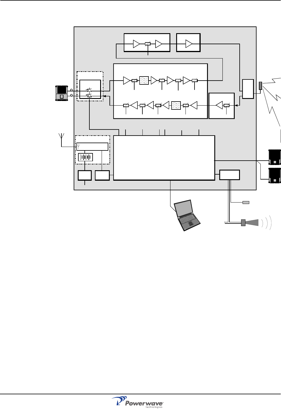
Figure A-2 WRH-V Block Diagram
Figure A-2 illustrates a block diagram the WRH-V. The WRH-V is always fed by a BTS via
either a BMU or an OCM. The TX signal from the BTS is converted to an optical signal in a
BMU or OCM and fed to the WRH-V via a fiber optic cable. The optical signal is received by
the FON and converted to an RF signal. The FON supervises the signaling and reports errors
via the RCU connected to the CU.
The RF signal enters the WBA at P1101, is amplified in a LNA and is then further amplified in
amplifier stages followed by controllable attenuators. The signal exits the WBA on P1401 and
enters the PA at P4 where it is amplified and fed to the DPX. The signal then goes through an
MCPA before being fed to the DPX. The amplified output signal passes the DPX before it is
fed to the service antenna.
The uplink signal path is located on the same WBA but has no PA or MCPA stage. An
optional LNA can be used.
FOU
FON
P102RX
TX
P101
P130
P31
P33
WBA
PA - DL
LNA
DPX
ALI / RCI
WLI
P34/
P36
P130
ANT
HI
LO
P1101 P1401
P4 P5
RCU
PSU
RCI
BMU
OCM
FLI
P4P3
MCPA
LNA
P2401 P2101
CU
DL
UL
LNA - UL
OUT1 IN