
User's Manual


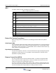
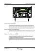


Table Of Contents
- Revision Record
- Table of Contents
- List of Figures
- List of Tables
- Abbreviations
- Chapter 1 Product Description
- Introduction
- Scope of Manual
- Safety
- Warning Signs
- Human Exposure of RF Radiation
- Radiation Safety Distances
- Electrostatic Discharge (ESD)
- Sub Unit Overview
- Wideband Amplifier PCBA (WBA)
- Power Amplifier PCBA (PA)
- Multi-Carrier Power Amplifier PCBA (MCPA)
- Booster Amplifier PCBA (BA)
- Distribution PCBA (DIA)
- Control Unit PCBA (CU)
- Low Noise Amplifier (LNA)
- Duplex Filter (DPX)
- Fiber Optic Unit (FOU)
- Fiber Optic Node (FON)
- Power Supply Unit (PSU)
- Remote Control Unit (RCU)
- Alarm Interface PCBA (ALI) and Remote Control Interface PCBA (RCI)
- Sub Unit Locations
- Fiber Optic Distribution Networks
- Multi-Operator Configurations
- Chapter 2 Controls, Indicators and Connectors
- Chapter 3 Installation
- Chapter 4 Maintenance
- Chapter 5 Specifications
- Appendix A Block Diagrams
Wideband Radio Head Repeater-to-Repeater Link (R2R)
044-05251 Rev A 4-11
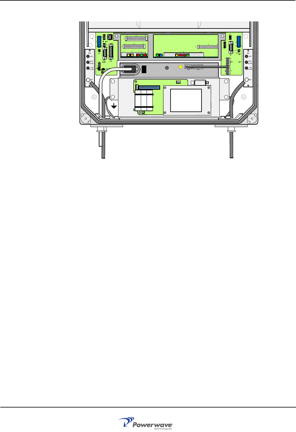
Figure 4-1 RCU in the WRH cabinet
RCU for Radio Communication
The RCU antenna for a radio modem is connected to the BS antenna via the uplink DC,
provided the RCU and the WRH operate in the same cell system. Otherwise, the modem
must have a separate antenna. Data is transferred between the WRH and the RCU via the
P130 modem port on the RCI or FON. The RCU is also powered via the same port and has a
battery with enough capacity to send a number of alarms if a main power failure occurs.
RCU for Telephone Line Communication
The land line version uses a telephone line connected to a terminal block on the RCU. A free
strain relief bushing at the bottom of the WRH is used for the external telephone line cable.
Repeater-to-Repeater Link (R2R)
This section briefly describes the R2R network. Node configuration for the R2R network is
described in the OM-Online User’s Manual. The R2R network is a Powerwave specific
network that can handle up to 13 nodes, one or several of which being a gateway for
communication with OM-Online or OMS via modem.
Sliding Window (SLW) is a Powerwave specific protocol developed for the R2R network. The
SLW protocol and the IP protocol do not support each other and they cannot be mixed in any
node.
MS
DPX
ANT
TES T
DC
-30 dB
-20 dB
MS
DPX
ANT
TEST
DC
-30 dB
-20 dB
ALLGON INNOV ATION
SWEDEN M105 R6
1
PARKING
FOR W 5
W5
8
P27
W6B 10
1
P33
ALARM
P23
LNA
UP-LINK
P32
MODEM
A
U
X
1
P28
DOOR
5
9
6
1
1
16
1
1
M
-
>
S
P11
P34
8
9
15
P26
15 16
S
-
>
M
1
2
3
89
P
3
6
5
X0A
X0B
2
V2
1
16
P12 P13
1
1
1
16
16
16
P4
P5
P6
c
b
a
c
b
a
c
b
a
c
b
a
1P232
1
b
a
1
16P3
16
1
16
P14
1
V1
1
1
1
1
1
4
6
1
15
6
9
15
2
16
1
2
4
5
8
5
P35
P21
PSU
6
10
P31
PC
P29
P24
P25
GND
7
6V6
LNA
DOWN- LINK
LED
P22
1
2
POWER SUPPLY UNIT
RCU