
User's Manual

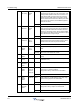

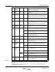

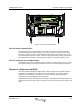


Table Of Contents
- Revision Record
- Table of Contents
- List of Figures
- List of Tables
- Abbreviations
- Chapter 1 Product Description
- Introduction
- Scope of Manual
- Safety
- Warning Signs
- Human Exposure of RF Radiation
- Radiation Safety Distances
- Electrostatic Discharge (ESD)
- Sub Unit Overview
- Wideband Amplifier PCBA (WBA)
- Power Amplifier PCBA (PA)
- Multi-Carrier Power Amplifier PCBA (MCPA)
- Booster Amplifier PCBA (BA)
- Distribution PCBA (DIA)
- Control Unit PCBA (CU)
- Low Noise Amplifier (LNA)
- Duplex Filter (DPX)
- Fiber Optic Unit (FOU)
- Fiber Optic Node (FON)
- Power Supply Unit (PSU)
- Remote Control Unit (RCU)
- Alarm Interface PCBA (ALI) and Remote Control Interface PCBA (RCI)
- Sub Unit Locations
- Fiber Optic Distribution Networks
- Multi-Operator Configurations
- Chapter 2 Controls, Indicators and Connectors
- Chapter 3 Installation
- Chapter 4 Maintenance
- Chapter 5 Specifications
- Appendix A Block Diagrams

Return For Service Procedures Wideband Radio Head
4-10 044-05251 Rev A
WRH
To replace a WRH, proceed as desribed in the Table 4-5.
Table 4-5 WRH Replacement Procedure
Return For Service Procedures
When returning products to Powerwave, the following procedures will ensure optimum
response.
Obtaining an RMA
A Return Material Authorization (RMA) number must be obtained prior to returning equipment
to the factory for service. Pease contact our Repair Department at 1-714-466-1000 to obtain
this number, or FAX your request to 1-714-466-5800. Failure to obtain this RMA number may
result in delays in receiving repair service.
Repackaging for Shipment
To ensure safe shipment of the unit, it is recommended that the original package designed for
shipping the unit be reused. If it is not available, contact Powerwave’s Customer Service
Department for packing materials.
Remote Control Unit (RCU)
The RCU provides remote control of Powerwave WRHs. It contains an integrated mobile
phone, modem and power supply backup. The RCU is installed in the bottom front of the
cabinet, on top of the PSU as illustrated in Figure 4-1.
The RCU is connected to P130 on either an RCI or FON. A jumper is required between pins 1
and 2 on the RCI if the P130 cable connector is disconnected. If a main power failure occurs,
the unit has a battery with enough capacity for sending a number of alarms.
Step Action
1 Open WRH door and secure
2 Disconnect main power plug from PSU
3 Verify all cables connected to WRH are labeled before disconnecting, then disconnect all
cables
4 Remove mounting screws from bottom legs of WRH and loosen mounting screws in top
legs
5 Close and secure door
WARNING: A fully loaded WRH can weigh 96lbs. Lifting of the WRH should be done by
two people. Do not attempt to carry the WRH up a ladder.
6 Lift the WRH off the mount hinges
7 Replace WRH in reverse order
8 Connect PC to OM Online port and verify configuration. For Fiber Optic installations, ver-
ify IP address.
9 Close WRH door and secure