
User's Manual

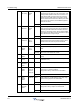

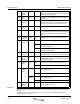


Table Of Contents
- Revision Record
- Table of Contents
- List of Figures
- List of Tables
- Abbreviations
- Chapter 1 Product Description
- Introduction
- Scope of Manual
- Safety
- Warning Signs
- Human Exposure of RF Radiation
- Radiation Safety Distances
- Electrostatic Discharge (ESD)
- Sub Unit Overview
- Wideband Amplifier PCBA (WBA)
- Power Amplifier PCBA (PA)
- Multi-Carrier Power Amplifier PCBA (MCPA)
- Booster Amplifier PCBA (BA)
- Distribution PCBA (DIA)
- Control Unit PCBA (CU)
- Low Noise Amplifier (LNA)
- Duplex Filter (DPX)
- Fiber Optic Unit (FOU)
- Fiber Optic Node (FON)
- Power Supply Unit (PSU)
- Remote Control Unit (RCU)
- Alarm Interface PCBA (ALI) and Remote Control Interface PCBA (RCI)
- Sub Unit Locations
- Fiber Optic Distribution Networks
- Multi-Operator Configurations
- Chapter 2 Controls, Indicators and Connectors
- Chapter 3 Installation
- Chapter 4 Maintenance
- Chapter 5 Specifications
- Appendix A Block Diagrams
Wideband Radio Head Troubleshooting
044-05251 Rev A 4-7
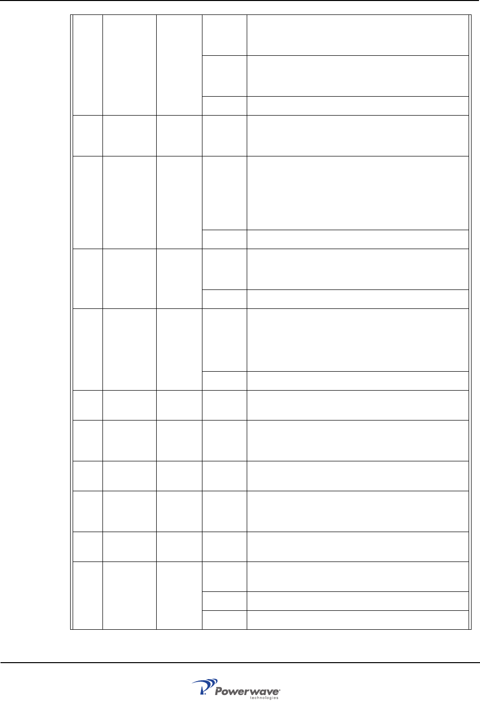
92 FON
RxLevel
alarm
FON Warning Received optical level is below any of the two limits
(one for Warning and one for Error). Suggested rem-
edy: Check optical cables.
Error Received optical level is below any of the two limits
(one for Warning and one for Error). Suggested rem-
edy: Check optical cables.
Ceasing The cause of the alarm has ceased.
93 FON SPI
alarm
FON
F2F
Error The SPI bus connection to the RF modem does not
work properly. Suggested remedy: Replace the FON
PCBA.
97 No GPS
signal
GPS Warning The GPS device cannot find any satellites. If active
antenna is used, then the power supply for it can be
faulty or wrongly configured. Suggested remedy:
Check the GPS antenna and cables. If an active
antenna is used, then the jumper switch should be set
accordingly.
Ceasing The cause of the alarm has ceased.
98 No GPS
device
GPS Error The GPS device cannot be detected although an
adapter PCBA is mounted. Suggested remedy:
Check the GPS PCBA.
Ceasing The cause of the alarm has ceased.
99 GPS
Antenna
power
GPS Error The power supply to the GPS antenna is faulty or
there is a power supply to a passive antenna.
Suggested remedy: Check the GPS antenna and
cables. If an active antenna is used, then the jumper
switch should be set accordingly.
Ceasing The cause of the alarm has ceased.
100 Startup
error
CHA # Error A hardware error is detected on the PCBA at power-
ing up.
101 Synthe-
sizer fault
CHA # Error Unlocked synthesizer. The frequency synthesizer is
unlocked and the transmission can take place on an
unknown frequency.
102 Volt Reg.
fault
CHA # Error DC voltage missing. A DC voltage to an analog part
of the PCBA is missing.
103 PA fault CHA # Error Low power amplifier gain. The PA PCBA has too low
output power for the RSSI and gain set. Not available
in all CU software versions.
104 Param R/
W error
CHA # Error EEPROM read or write failure on the PCBA.
105 High tem-
perature
CHA # Warning The CHA PCBA temperature is higher than 85°C.
Error The CHA PCBA temperature is higher than 95°C.
Ceasing The CHA PCBA temperature has fallen below 70°C.