
User's Manual
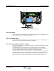

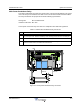


Table Of Contents
- Revision Record
- Table of Contents
- List of Figures
- List of Tables
- Abbreviations
- Chapter 1 Product Description
- Introduction
- Scope of Manual
- Safety
- Warning Signs
- Human Exposure of RF Radiation
- Radiation Safety Distances
- Electrostatic Discharge (ESD)
- Sub Unit Overview
- Wideband Amplifier PCBA (WBA)
- Power Amplifier PCBA (PA)
- Multi-Carrier Power Amplifier PCBA (MCPA)
- Booster Amplifier PCBA (BA)
- Distribution PCBA (DIA)
- Control Unit PCBA (CU)
- Low Noise Amplifier (LNA)
- Duplex Filter (DPX)
- Fiber Optic Unit (FOU)
- Fiber Optic Node (FON)
- Power Supply Unit (PSU)
- Remote Control Unit (RCU)
- Alarm Interface PCBA (ALI) and Remote Control Interface PCBA (RCI)
- Sub Unit Locations
- Fiber Optic Distribution Networks
- Multi-Operator Configurations
- Chapter 2 Controls, Indicators and Connectors
- Chapter 3 Installation
- Chapter 4 Maintenance
- Chapter 5 Specifications
- Appendix A Block Diagrams
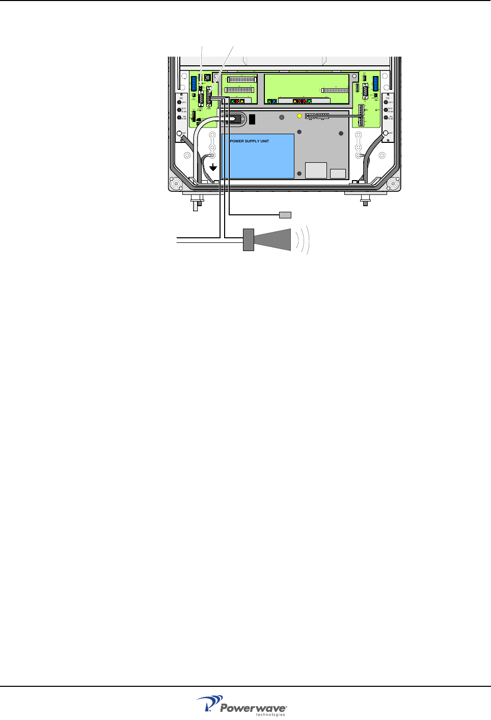
Wideband Radio Head Optional Connections
044-05251 Rev A 3-7
Figure 3-8 External alarm connection
Door Open Alarm
A door open alarm can be configured and installed in the WRH. This is arranged with a door
switch connected to P28, as illustrated in Figure 3-8.
Fiber Link Interface (FLI)
The FLI feature makes it possible to interconnect WRHs. By using an RF distribution fiber
network, no wire or other communication device is required.
Wire Link Interface (WLI) Network (IP to R2R)
Two types of WLI networks are available for the WRH: Internet Protocol (IP) and a Repeater-
to-Repeater Link (R2R).
The network cables are connected to the P34 or P36 WLI ports on the DIA PCBA as
illustrated in Figure 3-9. The cables can either be interconnected at the P1 terminal on the
connector PCBA located to the right in the cabinet or to both P34 and P36.
Any cable type can be used for indoor installations. For outdoor installations, the Li 2YC11Y,
2x2xAWG24/222, non-halogen, Metrofunkkabel-Union cable type is recommended. Use
strain relief bushings or connectors at the bottom of the WRH. If the link cable between two
WRHs is longer than 25 meters, an RS-485 WRH is required as illustrated Figure 3-10.
MS
DPX
ANT
TEST
DC
-30 dB
-20 dB
MS
DPX
ANT
TEST
DC
-30 dB
-20 dB
POWER SUPPLY UNIT
ALLGON INNOVATION
SWEDEN M105 R6
1
PARKING
FOR W5
W5
8
P27
W6B 10
1
P33
ALARM
P23
LNA
UP-LINK
P32
MODEM
A
U
X
1
P28
DOOR
5
9
6
1
1
16
1
1
M
-
>
S
P11
P34
8
9
15
P26
15 16
S
-
>
M
1
2
3
89
P
3
6
5
X0A
X0B
2
V2
1
16
P12 P13
1
1
1
16
16
16
P4
P5
P6
c
b
a
c
b
a
c
b
a
c
b
a
1P232
1
b
a
1
16P3
16
1
16
P14
1
V1
1
1
1
1
1
4
6
1
15
6
9
15
2
16
1
2
4
5
8
5
P35
P21
PSU
6
10
P31
PC
P29
P24
P25
GND
7
6V6
LNA
DOWN-LINK
LED
P22
1
2
P28 P33