
User's Manual

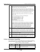


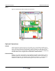
Table Of Contents
- Revision Record
- Table of Contents
- List of Figures
- List of Tables
- Abbreviations
- Chapter 1 Product Description
- Introduction
- Scope of Manual
- Safety
- Warning Signs
- Human Exposure of RF Radiation
- Radiation Safety Distances
- Electrostatic Discharge (ESD)
- Sub Unit Overview
- Wideband Amplifier PCBA (WBA)
- Power Amplifier PCBA (PA)
- Multi-Carrier Power Amplifier PCBA (MCPA)
- Booster Amplifier PCBA (BA)
- Distribution PCBA (DIA)
- Control Unit PCBA (CU)
- Low Noise Amplifier (LNA)
- Duplex Filter (DPX)
- Fiber Optic Unit (FOU)
- Fiber Optic Node (FON)
- Power Supply Unit (PSU)
- Remote Control Unit (RCU)
- Alarm Interface PCBA (ALI) and Remote Control Interface PCBA (RCI)
- Sub Unit Locations
- Fiber Optic Distribution Networks
- Multi-Operator Configurations
- Chapter 2 Controls, Indicators and Connectors
- Chapter 3 Installation
- Chapter 4 Maintenance
- Chapter 5 Specifications
- Appendix A Block Diagrams
Optional Connections Wideband Radio Head
3-6 044-05251 Rev A
WRH-V
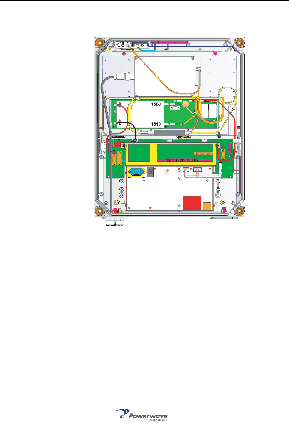
Figure 3-7 illustrates the WRH-V cables and connections.
Figure 3-7 WRH-V Cable Connections
Optional Connections
Alarms
Alarm signals from external sensors are received by an ALI or RCI which forwards them to
the CU. The RCI is used if the WRH has an RCU, otherwise the ALI is used. The software on
the CU can activate acoustic or visual alarms or direct the alarm to the P33 alarm port for
forwarding via an RCU to an OM-Online or OMS workstation. Alarms can also be handled by
the FON. Alarms can be configured from an OM-Online or OMS workstation.
External Alarm
Burglary, fire or other external alarms can be handled by the WRH. External alarm sensors
and alarm signals are connected to the P33 alarm port located to the left in the cabinet, as
illustraated in Figure 3-8. The P33 alarm port is described in Chapter 2. The cable for this
installation is taken through a strain relief bushing at the bottom of the WRH cabinet.