
User's Manual


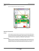
Table Of Contents
- Revision Record
- Table of Contents
- List of Figures
- List of Tables
- Abbreviations
- Chapter 1 Product Description
- Introduction
- Scope of Manual
- Safety
- Warning Signs
- Human Exposure of RF Radiation
- Radiation Safety Distances
- Electrostatic Discharge (ESD)
- Sub Unit Overview
- Wideband Amplifier PCBA (WBA)
- Power Amplifier PCBA (PA)
- Multi-Carrier Power Amplifier PCBA (MCPA)
- Booster Amplifier PCBA (BA)
- Distribution PCBA (DIA)
- Control Unit PCBA (CU)
- Low Noise Amplifier (LNA)
- Duplex Filter (DPX)
- Fiber Optic Unit (FOU)
- Fiber Optic Node (FON)
- Power Supply Unit (PSU)
- Remote Control Unit (RCU)
- Alarm Interface PCBA (ALI) and Remote Control Interface PCBA (RCI)
- Sub Unit Locations
- Fiber Optic Distribution Networks
- Multi-Operator Configurations
- Chapter 2 Controls, Indicators and Connectors
- Chapter 3 Installation
- Chapter 4 Maintenance
- Chapter 5 Specifications
- Appendix A Block Diagrams

044-05251 Rev A 3-1
Chapter 3
Installation
Introduction
This chapter contains unpacking, inspection and installation instructions for installing and
powering up the WRH.
Site Survey
Powerwave recommends that a site survey be performed prior to equipment ordering or
installation. Performing a detailed site survey reduces or eliminates installation and turn-up
delays. Pay particular attention to power plant capacity, cooling needs, floor space, and RF/
DC cabling/breaker requirements. Cabinet dimensions, clearance dimensions, and weights
are listed in Chapter 5.
Unpacking and Inspection
This equipment has been operated, tested, and calibrated at the factory. Carefully open
containers to remove equipment. Retain all packing material that can be reassembled in the
event unit must be returned to the factory. Perform the following steps:
• Visually inspect equipment for damage that may have occurred during shipment. If pos-
sible, in the presence of the delivery person.
• Check for evidence of water damage, bent or warped chassis, loose screws or nuts, or
extraneous packing material in connectors.
If equipment is damaged, file a claim with the carrier once the extent of any damage is
assessed.
If equipment must be returned to factory, please contact factory for a Return Material
Authorization (RMA). See Chapter 4.
WRH Location
The WRH is designed with a weather proof outdoor cabinet that can be mounted without any
kind of shelter from rain, snow or hail. The same unit can be installed indoors. A preferable
site for the WRH is a location free of obstructions, easily accessable and allows for proper air-
flow and ventilation.
If a WRH is installed outdoor and can be exposed to direct sunshine, it is essential that air
can circulate around the WRH with no obstacle. The operating temperature must not exceed
131°F (55°C). A shelter can be used to shade the WRH from direct sunshine.
Never open a WRH when rain, snow, hail, high humidity or high winds are present unless
some kind of temporary shelter can be erected. Limitations for very bad weather are found in
the next section.
Mounting
The WRH is easy to mount using the provided mounting bracket, which has 9/16” (14mm)
holes for 3/8” (10mm) or 1/2” (12mm) fixing screws. Clamps with C-C measures of 3.5”
(90mm), 5.3” (135mm), 5.7” (144mm), 8.1” (205mm), 9.8” (250mm), and 11.8” (300mm) can
be used as well. The vertical C-C measure for these are 16.2” (411mm). There is a 9/16”
(14mm) single hole in the middle of the mounting bracket, marked ‘A’ in the figure, which is
intended for a locking screw to lock the bracket into place.