
User's Manual


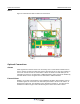
Table Of Contents
- Revision Record
- Table of Contents
- List of Figures
- List of Tables
- Abbreviations
- Chapter 1 Product Description
- Introduction
- Scope of Manual
- Safety
- Warning Signs
- Human Exposure of RF Radiation
- Radiation Safety Distances
- Electrostatic Discharge (ESD)
- Sub Unit Overview
- Wideband Amplifier PCBA (WBA)
- Power Amplifier PCBA (PA)
- Multi-Carrier Power Amplifier PCBA (MCPA)
- Booster Amplifier PCBA (BA)
- Distribution PCBA (DIA)
- Control Unit PCBA (CU)
- Low Noise Amplifier (LNA)
- Duplex Filter (DPX)
- Fiber Optic Unit (FOU)
- Fiber Optic Node (FON)
- Power Supply Unit (PSU)
- Remote Control Unit (RCU)
- Alarm Interface PCBA (ALI) and Remote Control Interface PCBA (RCI)
- Sub Unit Locations
- Fiber Optic Distribution Networks
- Multi-Operator Configurations
- Chapter 2 Controls, Indicators and Connectors
- Chapter 3 Installation
- Chapter 4 Maintenance
- Chapter 5 Specifications
- Appendix A Block Diagrams
PCBA Connectors Wideband Radio Head
044-05251 Rev A 2-9
PSU
The PSU is located in the bottom middle of the cabinet or in an equipped high cover. The
PSU has all the voltages required for the WRH. It has capacity for the radio circuitry, fiber
optics, modem, etc., and also supplies the BA if used. Multi-band WRH-Vs always require a
second PSU. There are two PSU types with different input voltages:
1. 115/230V 50/60Hz, 300W input max.
2. 21- 60V DC, 300W input max.
The DIA provides most of the internal connection between the sub units and external ports.
Connectors involved in the installation are also located on the DIA. Table 2-13 describes
these connections.
Figure 2-9 PSU Location
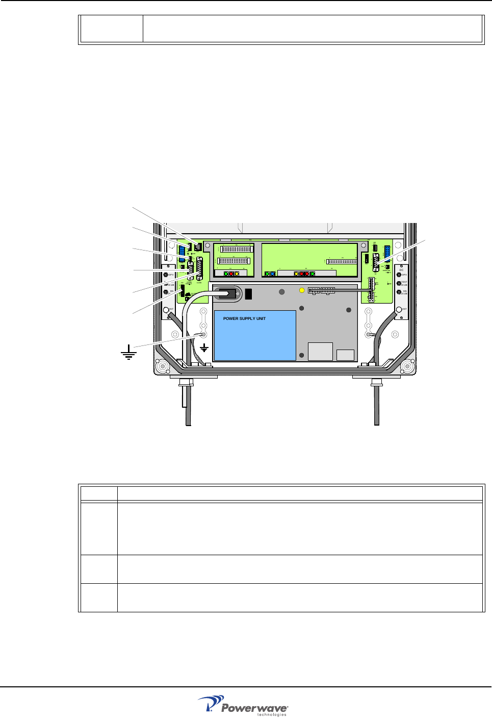
Table 2-11 PSU Connectors
P130 34-pin, 2-line male, RCU port used for connecting an RCU. The connec-
tor contains both the modem connection and RCU power supply.
Port Description
P27 Auxiliary Port (8-pin male) - Used to power the old RCU. It is located on the DIA
to the left in the cabinet. Pins 2 and 3 must always be interconnected to provide
the CU and ALI/RCI PCBs with voltage supply. If there is no cable connected,
pins 2 and 3 must be interconnected with a jumper.
P31 RS-232 PC Port (9-pin D-sub female) - Used for local PC communication. It is
located on the DIA to the right in the cabinet.
P32 RS-232 Modem port (9-pin D-sub male) - V.24 interface used for the old RCU.
It is located on the DIA to the left in the cabinet.
MS
DPX
ANT
TEST
DC
-30 dB
-20 dB
MS
DPX
ANT
TEST
DC
-30 dB
-20 dB
POWER SUPPLY UNIT
AL LGON INNOVATI ON
SWEDEN M105 R6
1
PARKI NG
FOR W5
W5
8
P27
W6B 10
1
P33
ALARM
P23
LNA
UP-LINK
P32
MODEM
A
U
X
1
P28
DOOR
5
9
6
1
1
16
1
1
M
-
>
S
P11
P34
8
9
15
P26
15 16
S
-
>
M
1
2
3
89
P
3
6
5
X0A
X0B
2
V2
1
16
P12 P13
1
1
1
16
16
16
P4
P5
P6
c
b
a
c
b
a
c
b
a
c
b
a
1P232
1
b
a
1
16P3
16
1
16
P14
1
V1
1
1
1
1
1
4
6
1
15
6
9
15
2
16
1
2
4
5
8
5
P35
P21
PSU
6
10
P31
PC
P29
P24
P25
GND
7
6V6
LNA
DOWN- LINK
LED
P22
1
2
P33
P27
P3
1
P32
P34
P28
P36