
User's Manual
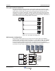


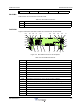

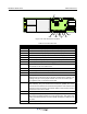
Table Of Contents
- Revision Record
- Table of Contents
- List of Figures
- List of Tables
- Abbreviations
- Chapter 1 Product Description
- Introduction
- Scope of Manual
- Safety
- Warning Signs
- Human Exposure of RF Radiation
- Radiation Safety Distances
- Electrostatic Discharge (ESD)
- Sub Unit Overview
- Wideband Amplifier PCBA (WBA)
- Power Amplifier PCBA (PA)
- Multi-Carrier Power Amplifier PCBA (MCPA)
- Booster Amplifier PCBA (BA)
- Distribution PCBA (DIA)
- Control Unit PCBA (CU)
- Low Noise Amplifier (LNA)
- Duplex Filter (DPX)
- Fiber Optic Unit (FOU)
- Fiber Optic Node (FON)
- Power Supply Unit (PSU)
- Remote Control Unit (RCU)
- Alarm Interface PCBA (ALI) and Remote Control Interface PCBA (RCI)
- Sub Unit Locations
- Fiber Optic Distribution Networks
- Multi-Operator Configurations
- Chapter 2 Controls, Indicators and Connectors
- Chapter 3 Installation
- Chapter 4 Maintenance
- Chapter 5 Specifications
- Appendix A Block Diagrams
Wideband Radio Head PCBA Connectors
2-8 044-05251 Rev A
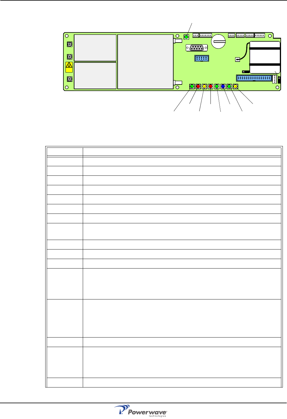
Figure 2-8 FON Connector Locations
Table 2-10 FON Connectors
Port Description
P101 SMA, electrical RF input port (to the optical TX port)
P107 SMA, electrical RF input port (15dB below the P101 port)
P102 SMA, electrical RF output port (from the optical RX port)
P103 SMA, electrical RF output port (15dB below the P102 port)
RX DIN/APC, optical input port (to the P102 and P103 RF ports)
TX DIN/APC, optical output port (from the P101 RF port)
P104 Used only for development and debugging
P105 4-pin male, door LED indicators. Used for the yellow and red LED indica-
tors located on the front cabinet door
P106 9-pin D-sub female, RS-232 used for local PC communication
P108/116 6-pin male, parallel connected power ports for the FON
P109 7-pin male, used for external alarm sensors
P110 W-link jumper, used to terminate units in a W-link. It has to be set in the
parking state for all units except for the first and last units in a W-link. The
Parking state (P) has the jumper between the center and bottom pins.
The opposite state (T) terminates the W-link.
P111/112 5-pin male, WLI ports used for interconnecting nodes in WLI-nets (IP or
R2R networks). They are identical and connected in parallel. One of the
connectors are intended to be used from the previous node and the other
connector to the next node in the network. Either can be used for the first
and the last unit in the net chain.
P113 2-pin male, used for the on-PCBA backup batteries.
P114 Backup power output jumper, sets the backup power output state. The
OFF state has jumper between the center and left pins. This jumper has
to be in the OFF state when used in an OCM. Otherwise, it shall be in the
ON state.
P115 3-pin male, future port - intended for future use
P102
P130
Beryll ium
oxide
hazard
P103
P101
P114
P108P116P111
P105P109P115
P106
P104
RX
TX
P113
P112
P110
OPER
FAULT
POWER
BOOT
WLI/R2R
DATA
BATT
CHARGE
FLI