
User's Manual
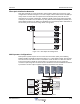


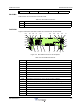
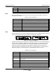

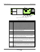
Table Of Contents
- Revision Record
- Table of Contents
- List of Figures
- List of Tables
- Abbreviations
- Chapter 1 Product Description
- Introduction
- Scope of Manual
- Safety
- Warning Signs
- Human Exposure of RF Radiation
- Radiation Safety Distances
- Electrostatic Discharge (ESD)
- Sub Unit Overview
- Wideband Amplifier PCBA (WBA)
- Power Amplifier PCBA (PA)
- Multi-Carrier Power Amplifier PCBA (MCPA)
- Booster Amplifier PCBA (BA)
- Distribution PCBA (DIA)
- Control Unit PCBA (CU)
- Low Noise Amplifier (LNA)
- Duplex Filter (DPX)
- Fiber Optic Unit (FOU)
- Fiber Optic Node (FON)
- Power Supply Unit (PSU)
- Remote Control Unit (RCU)
- Alarm Interface PCBA (ALI) and Remote Control Interface PCBA (RCI)
- Sub Unit Locations
- Fiber Optic Distribution Networks
- Multi-Operator Configurations
- Chapter 2 Controls, Indicators and Connectors
- Chapter 3 Installation
- Chapter 4 Maintenance
- Chapter 5 Specifications
- Appendix A Block Diagrams
Wideband Radio Head PCBA Indicators
2-2 044-05251 Rev A
PCBA Indicators
This following paragraphs describe the LED indicators on the main PCBAs inside the WRH.
CU PCBA
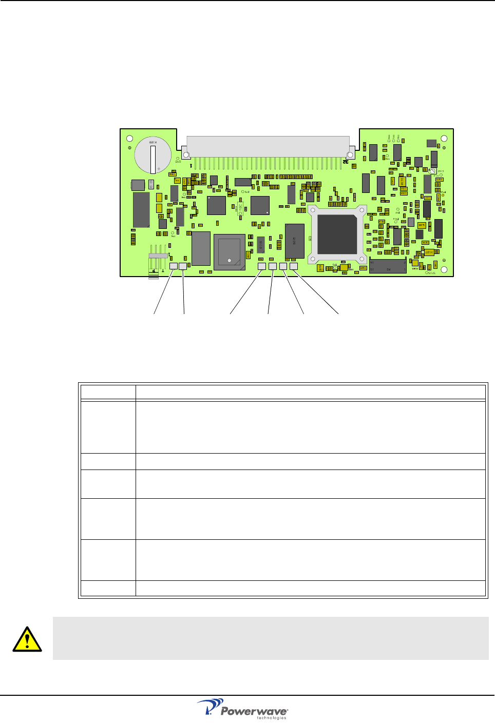
Figure 2-3 illustrates the ocation of the LEDs on the CU and Table 2-1 describes their
indications.
Figure 2-3 CU PCBA Indicators
Table 2-1 CU PCBA LED Indicators
LED Description
WLI Wire Line Interface. A flashing green LED indicates the unit is receiving
data over the subcarrier. A steady green LED indicates: the unit is currently
not receiving any data, is currently not a control station or there is no other
node in the network.
DATA Blue LED indicating data transmission in the W-net.
POWER Yellow LED indicating present power and remains steady after power is
switched on.
BOOT Steady red LED when the CU boots (10 – 15 seconds after main power is
switched on), then flashing red (5 – 10 seconds), then off if no error is
detected. If an error is detected LED will stay on.
FAULT Flashing red LED for 15 – 20 seconds after main power is switched on.
Flashes for less serious alarms (Error) and is on solid for fatal alarms (Crit-
ical).
OPER Steady green LED indicates WRH is ready for operation.
WARNING: A lithium battery is permanently mounted on the CU PCBA. Due to risk of
explosion, this battery must not be removed. In case of battery malfunction, replace the
CU PCB.
WLI DATA POWER BOOT FAULT OPER