
User's Manual
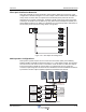


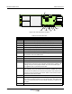
Table Of Contents
- Revision Record
- Table of Contents
- List of Figures
- List of Tables
- Abbreviations
- Chapter 1 Product Description
- Introduction
- Scope of Manual
- Safety
- Warning Signs
- Human Exposure of RF Radiation
- Radiation Safety Distances
- Electrostatic Discharge (ESD)
- Sub Unit Overview
- Wideband Amplifier PCBA (WBA)
- Power Amplifier PCBA (PA)
- Multi-Carrier Power Amplifier PCBA (MCPA)
- Booster Amplifier PCBA (BA)
- Distribution PCBA (DIA)
- Control Unit PCBA (CU)
- Low Noise Amplifier (LNA)
- Duplex Filter (DPX)
- Fiber Optic Unit (FOU)
- Fiber Optic Node (FON)
- Power Supply Unit (PSU)
- Remote Control Unit (RCU)
- Alarm Interface PCBA (ALI) and Remote Control Interface PCBA (RCI)
- Sub Unit Locations
- Fiber Optic Distribution Networks
- Multi-Operator Configurations
- Chapter 2 Controls, Indicators and Connectors
- Chapter 3 Installation
- Chapter 4 Maintenance
- Chapter 5 Specifications
- Appendix A Block Diagrams

044-05251 Rev A 2-1
Chapter 2
Controls, Indicators and Connectors
Introduction
This chapter contains descriptions of the WRH controls, indicators and connectors.
Front Cover Indicators
Figure 2-1 External Indicators
Two LEDs are located on the front cover to provide easy identification of a fault in the system.
The amber operation LED lights up approximately 15 seconds after the main power is
switched on. When the LED is steady, the WRH is ready for operation. The red alarm LED
indicates a system error alarms when flashing and a critical alarm when steady.
Cabinet Indicators
Figure 2-2 Cabinet Internal Indicators
Figure 2-2 illustrates the LED indicators located on the ALI, or RCI, and CU PCBAs as well as
the 115/220V main power switch (‘S’) in the cabinet. These indicators are described in further
detail in the following sections.
Red
Amber
MS
DPX
ANT
TEST
DC
-30 dB
-20 dB
MS
DPX
ANT
TEST
DC
-30 dB
-20 dB
ALLGON INN OVATION
SWE DEN M 105 R6
1
PARKING
FOR W5
W5
8
P27
W6B 10
1
P33
ALARM
P23
LNA
UP-LINK
P32
MODEM
A
U
X
1
P28
DOOR
5
9
6
1
1
16
1
1
M
-
>
S
P11
P34
8
9
15
P26
15 16
S
-
>
M
1
2
3
89
P
3
6
5
X0A
X0B
2
V2
1
16
P12 P13
1
1
1
16
16
16P4
P5
P6
c
b
a
c
b
a
c
b
a
c
b
a
1P232
1
b
a
1
16P3
16
1
16
P14
1
V1
1
1
1
1
1
4
6
1
15
6
9
15
2
16
1
2
4
5
8
5
P35
P21
PSU
6
10
P31
PC
P29
P24
P25
GND
7
6V6
LNA
DOWN-LINK
LED
P22
1
2
POWER SUPPLY UNIT
C
U
ALI
or
RCI
S
V
OPER
FAULT
POWER
10V
ALARM
POWER
BOOT
FAULT
OPER
WLI / R2R
DATA