
User's Manual
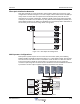


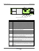
Table Of Contents
- Revision Record
- Table of Contents
- List of Figures
- List of Tables
- Abbreviations
- Chapter 1 Product Description
- Introduction
- Scope of Manual
- Safety
- Warning Signs
- Human Exposure of RF Radiation
- Radiation Safety Distances
- Electrostatic Discharge (ESD)
- Sub Unit Overview
- Wideband Amplifier PCBA (WBA)
- Power Amplifier PCBA (PA)
- Multi-Carrier Power Amplifier PCBA (MCPA)
- Booster Amplifier PCBA (BA)
- Distribution PCBA (DIA)
- Control Unit PCBA (CU)
- Low Noise Amplifier (LNA)
- Duplex Filter (DPX)
- Fiber Optic Unit (FOU)
- Fiber Optic Node (FON)
- Power Supply Unit (PSU)
- Remote Control Unit (RCU)
- Alarm Interface PCBA (ALI) and Remote Control Interface PCBA (RCI)
- Sub Unit Locations
- Fiber Optic Distribution Networks
- Multi-Operator Configurations
- Chapter 2 Controls, Indicators and Connectors
- Chapter 3 Installation
- Chapter 4 Maintenance
- Chapter 5 Specifications
- Appendix A Block Diagrams
Overview Wideband Radio Head
044-05251 Rev A 1-11
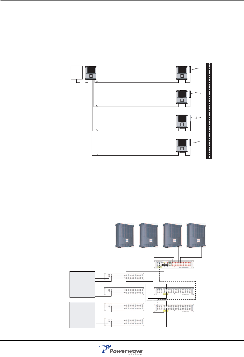
Fiber Optic Distribution Networks
Fiber optic networks are setup identically to data networks. WRHs are connected is a star
configuration as illustrated in Figure 1-6. In this example, a Base Station Master Unit (BMU) is
fed by a BTS via an RF cable. An Optical Converter Module (OCM) could also be used
depending on the system configuration. The BMU or OCM contain three FONs and provide
continuity to the FONs in the four WRHs. By using Wave Division Multiplexers (WDMs) and
Optical Splitters (OSPs) in the WRHs, the distribution net can be built up with a combination of
star and daisy-chain connections using double or single fiber.
Figure 1-10 Fiber Optic Star Configuration
Multi-Operator Configurations
Multi-operator systems require the use of Point of Interconnects (POIs), RF Combining
Modules (RCMs) and OCMs as illustrated in Figure 1-7. In this simple example, two operators
have two sectors each. Each sector is connected to a POI and then to a RCM. The RCM is
interconnected with an OCM via coaxial cables. The combined DL and UL signals are
converted to optical signals in the OCM and then distributed to the ARs. Additional information
is provided in the Fiber Optic Equipment Operation and Maintenance Manual.
Figure 1-11 Multi-operator System
BMU WRH
WRH
WRH
WRH
BTS
RF
O
p
erator 1
O
p
erator 2
Sector 1
Sector 1
Sector 2
Sector 2
OCM
RCM
RCM
POI
POI
POI
POI