
User's Manual


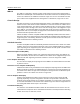


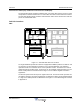
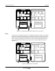
Table Of Contents
- Revision Record
- Table of Contents
- List of Figures
- List of Tables
- Abbreviations
- Chapter 1 Product Description
- Introduction
- Scope of Manual
- Safety
- Warning Signs
- Human Exposure of RF Radiation
- Radiation Safety Distances
- Electrostatic Discharge (ESD)
- Sub Unit Overview
- Wideband Amplifier PCBA (WBA)
- Power Amplifier PCBA (PA)
- Multi-Carrier Power Amplifier PCBA (MCPA)
- Booster Amplifier PCBA (BA)
- Distribution PCBA (DIA)
- Control Unit PCBA (CU)
- Low Noise Amplifier (LNA)
- Duplex Filter (DPX)
- Fiber Optic Unit (FOU)
- Fiber Optic Node (FON)
- Power Supply Unit (PSU)
- Remote Control Unit (RCU)
- Alarm Interface PCBA (ALI) and Remote Control Interface PCBA (RCI)
- Sub Unit Locations
- Fiber Optic Distribution Networks
- Multi-Operator Configurations
- Chapter 2 Controls, Indicators and Connectors
- Chapter 3 Installation
- Chapter 4 Maintenance
- Chapter 5 Specifications
- Appendix A Block Diagrams
Wideband Radio Head Overview
1-10 044-05251 Rev A
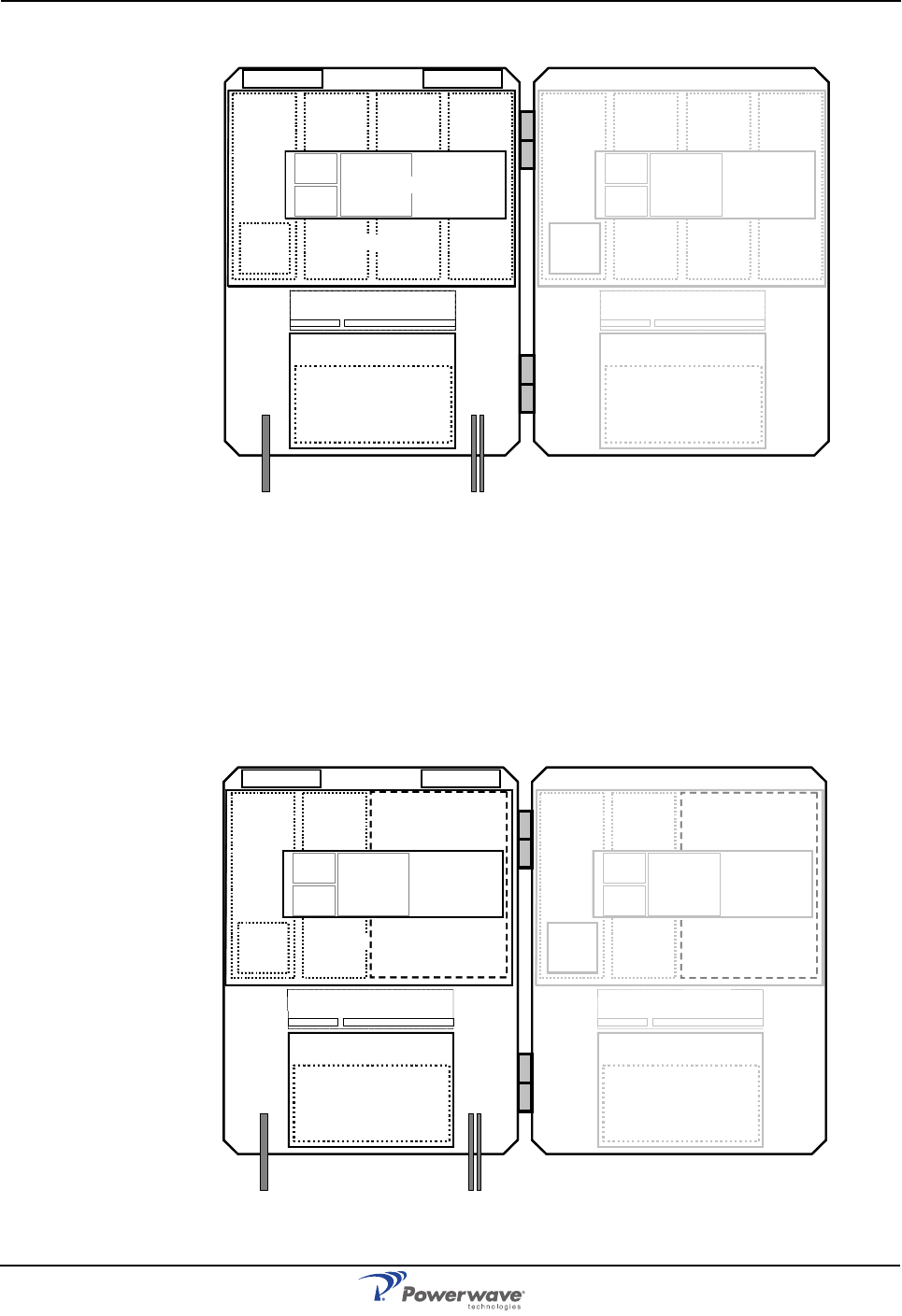
Figure 1-8 Standard WRH with Booster Option Sub Unit Locations
WRH-V
The WRH-V has a configuration similar to the standard WRH with the exception of a the MCPA
that boosts the ouput DL signal from the PA. The MCPA is located at positions 3 and 4 in the
cabinet. The MCPA requires an additional heat sink and is attached to the MCPA PCBA. A
WRH-V can only be equipped for one band in the cabinet and an additional band in a high
cover. PCBA positions are illustrated in the Figure 1-5 and a block diagram is located in
Appendix A.
Figure 1-9 WRH-V Sub Unit Locations
LNA - DL
1234
LNA - UL
PSU
(RCU)
DPX
CUALI/RCI
WBA
DL/UL
FOU
PA
DL
BA
DL
FON
5678
PSU
(RCU)
DPX
CUALI/RCI
WBA
DL/UL
FOU
PA
DL
BA
DL
FON
LNA - DL
1234
LNA - UL
PSU
(RCU)
DPX
CUALI/RCI
WBA
DL/UL
FOU
PA
DL
MCPA
DL
5678
PSU
(RCU)
DPX
CUALI/RCI
WBA
DL/UL
FOU
PA
DL
MCPA
DL
FON FON