
User's Manual


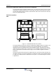
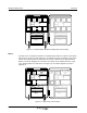
Table Of Contents
- Revision Record
- Table of Contents
- List of Figures
- List of Tables
- Abbreviations
- Chapter 1 Product Description
- Introduction
- Scope of Manual
- Safety
- Warning Signs
- Human Exposure of RF Radiation
- Radiation Safety Distances
- Electrostatic Discharge (ESD)
- Sub Unit Overview
- Wideband Amplifier PCBA (WBA)
- Power Amplifier PCBA (PA)
- Multi-Carrier Power Amplifier PCBA (MCPA)
- Booster Amplifier PCBA (BA)
- Distribution PCBA (DIA)
- Control Unit PCBA (CU)
- Low Noise Amplifier (LNA)
- Duplex Filter (DPX)
- Fiber Optic Unit (FOU)
- Fiber Optic Node (FON)
- Power Supply Unit (PSU)
- Remote Control Unit (RCU)
- Alarm Interface PCBA (ALI) and Remote Control Interface PCBA (RCI)
- Sub Unit Locations
- Fiber Optic Distribution Networks
- Multi-Operator Configurations
- Chapter 2 Controls, Indicators and Connectors
- Chapter 3 Installation
- Chapter 4 Maintenance
- Chapter 5 Specifications
- Appendix A Block Diagrams
Overview Wideband Radio Head
044-05251 Rev A 1-9
Alarm Interface PCBA (ALI) and Remote Control Interface PCBA (RCI)
The ALI handles alarms and alarm communication. It is replace with an RCI if an RCU is used
and provides an interface between the CU and an RCU for remote communication via modem.
The RCI also handles alarms and alarm communication. Either unit is located in the lower left
part of the shielded DIA frame.
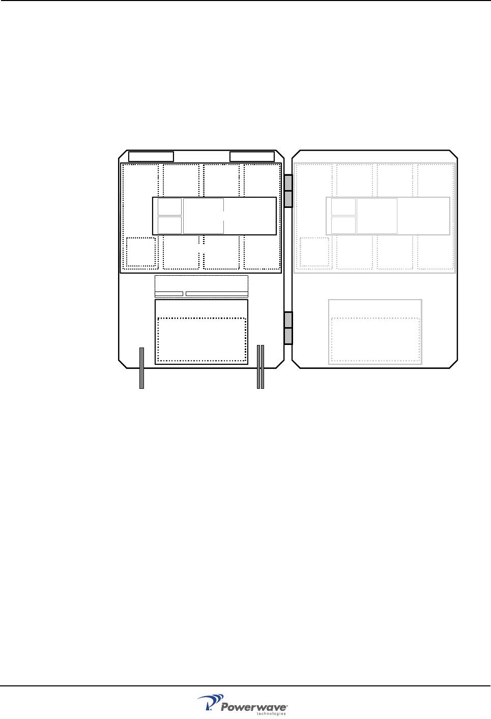
Sub Unit Locations
WRH
Figure 1-7 Standard WRH Sub Unit Locations
For single wideband operation the cabinet is equipped with a WBA in position 1 for both DL and
UL paths and an associated PA in position 2 for DL signal amplification. For dual band
operation another set of PCBAs can be used in positions 3 and 4. The WRH has a FON for
uplink transmission via fiber optics. A high cover can be equipped as well providing up to four
bands. PCBA positions are illustrated in the Figure 1-3 and a block diagram is located in
Appendix A.
The booster option boosts the ouput DL signal from the PA. The BA is located at position 3 in
the cabinet. A booster can only be equipped for one band in the cabinet and an additional band
in a high cover. PCBA positions are illustrated in the Figure 1-4 and a block diagram is located
in Appendix A.
LNA - DL
1234
LNA - UL
PSU
(RCU)
DPX
CUALI/RCI
WBA
DL/UL
FOU
PA
DL
FON
5678
PSU
(RCU)
DPX
WBA
DL/UL
FOU
PA
DL
FON
WBA
DL/UL
PA
DL
WBA
DL/UL
PA
DL