
User's Manual


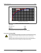

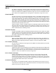


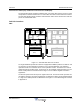
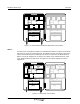
Table Of Contents
- Revision Record
- Table of Contents
- List of Figures
- List of Tables
- Abbreviations
- Chapter 1 Product Description
- Introduction
- Scope of Manual
- Safety
- Warning Signs
- Human Exposure of RF Radiation
- Radiation Safety Distances
- Electrostatic Discharge (ESD)
- Sub Unit Overview
- Wideband Amplifier PCBA (WBA)
- Power Amplifier PCBA (PA)
- Multi-Carrier Power Amplifier PCBA (MCPA)
- Booster Amplifier PCBA (BA)
- Distribution PCBA (DIA)
- Control Unit PCBA (CU)
- Low Noise Amplifier (LNA)
- Duplex Filter (DPX)
- Fiber Optic Unit (FOU)
- Fiber Optic Node (FON)
- Power Supply Unit (PSU)
- Remote Control Unit (RCU)
- Alarm Interface PCBA (ALI) and Remote Control Interface PCBA (RCI)
- Sub Unit Locations
- Fiber Optic Distribution Networks
- Multi-Operator Configurations
- Chapter 2 Controls, Indicators and Connectors
- Chapter 3 Installation
- Chapter 4 Maintenance
- Chapter 5 Specifications
- Appendix A Block Diagrams
Wideband Radio Head Overview
1-8 044-05251 Rev A
Signals from the DPX output are fed to the LNA input connector IN. OUT1 and OUT2 outputs
feed the WBAs of the same signal direction. The signal level in these connectors are +20dB
referenced to the antenna input. Another output, OUT LOW, is an expansion output for an
additional LNA if the WRH is equipped in the cover part of the chassis. The gain to this
connector is +2dB. The +7V input is used for +7V supply from the DIA PCBA and ATT is a
control signal for a controllable attenuator in the LNA.
Duplex Filter (DPX)
DPXs are located on the metal cover sheet in the upper part of the cabinet. Service and donor
DPXs are identical.
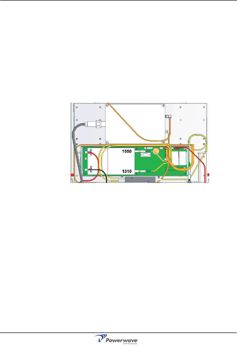
Fiber Optic Unit (FOU)
The FOU is a metal plate mounted on top of the cover plate in the upper part of the WRH. The
FON and fiber optic connectors are mounted on the FOU. It can also be configured with
combiners, splitters, and WDMs to obtain a desired combination of several branches with
double or single fiber.
Figure 1-6 Fiber Optic Unit (FOU)
Fiber Optic Node (FON)
The FON is the main part of the FOU. It is a bi-directional electrical/optical signal converter and
a node in a fiber network. In addition, the FON has all the functionality included in the CU
PCBA and contains battery backup. It has also functionality for:
• Electrical and optical signal supervision
• Internal and external alarm handling
• RS232 interface for local PC control via an O&M software (OM-Online)
• Remote control via an O&M software (OM-Online or OMS)
• Interfaces for RCU, WLI, and FLI
• Battery backup with charger
There are two versions of the FON; a 3-port and 4-port version. The FON has coaxial ports and
two optical ports for the downlink and uplink RF signal. The 4-port version has an additional
coaxial port on the left side.
Power Supply Unit (PSU)
A PSU is located in the lower center of the cabinet and, if configured, in the lower center of the
high cover.
Remote Control Unit (RCU)
The RCU is an optional communication unit for remote control of WRHs via PSTN or RF
modems. RCU types and details are described in Chapter 4.