
User's Manual


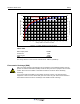

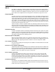


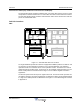
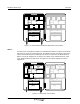
Table Of Contents
- Revision Record
- Table of Contents
- List of Figures
- List of Tables
- Abbreviations
- Chapter 1 Product Description
- Introduction
- Scope of Manual
- Safety
- Warning Signs
- Human Exposure of RF Radiation
- Radiation Safety Distances
- Electrostatic Discharge (ESD)
- Sub Unit Overview
- Wideband Amplifier PCBA (WBA)
- Power Amplifier PCBA (PA)
- Multi-Carrier Power Amplifier PCBA (MCPA)
- Booster Amplifier PCBA (BA)
- Distribution PCBA (DIA)
- Control Unit PCBA (CU)
- Low Noise Amplifier (LNA)
- Duplex Filter (DPX)
- Fiber Optic Unit (FOU)
- Fiber Optic Node (FON)
- Power Supply Unit (PSU)
- Remote Control Unit (RCU)
- Alarm Interface PCBA (ALI) and Remote Control Interface PCBA (RCI)
- Sub Unit Locations
- Fiber Optic Distribution Networks
- Multi-Operator Configurations
- Chapter 2 Controls, Indicators and Connectors
- Chapter 3 Installation
- Chapter 4 Maintenance
- Chapter 5 Specifications
- Appendix A Block Diagrams
Overview Wideband Radio Head
044-05251 Rev A 1-7
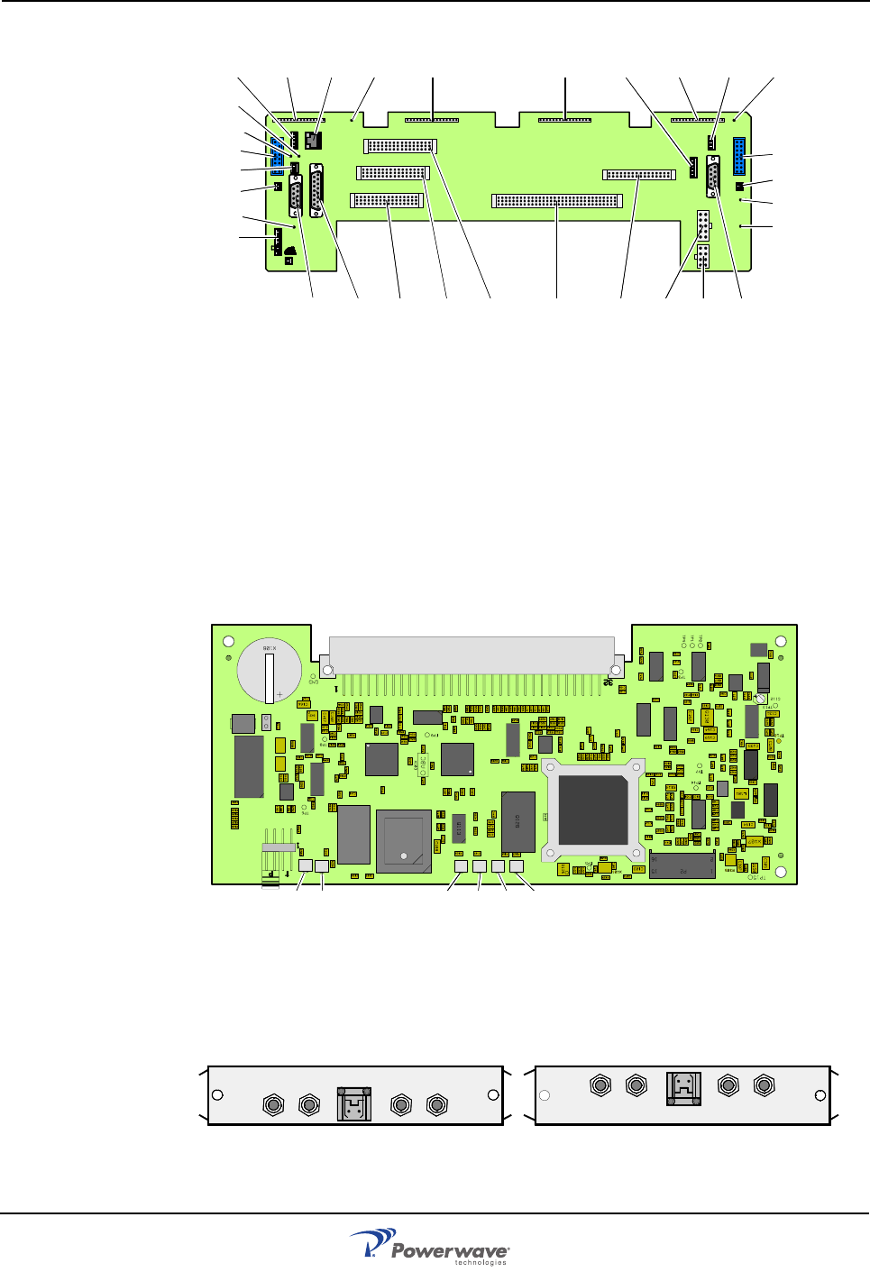
Figure 1-3 DIA PCBA
Control Unit PCBA (CU)
The CU is the core microprocesor controller in the WRH and is connected to P2 on the DIA. It
contains a microprocessor, main memory, flash memory for the CU software, EEPROM
memory for parameters, memory for the event log and statistics, a REFO reference oscillator,
ports for local and remote communication, battery powered real-time clock, and MAC identity
circuit. The CU supervises and controls operational parameters such as gain control and
channel handling, alarms, event log, password and logon. The CU is also a control interface for
OM-Online and OMS. Software for the CU can be downloaded from OM-Online, either locally
or remotely, or from OMS. It is located in the lower right part of the shielded DIA frame.
Figure 1-4 CU PCBA
Low Noise Amplifier (LNA)
LNAs are used as uplink low noise branch amplifiers and are located at the top of the cabinet
and the high cover, if equipped. LNA/UL is located to the left and LNA/DL to the right. All
coaxial connectors are SMA-type.
Figure 1-5 LNAs
ALLGON INNOVATION
SWEDEN M105 R6
1
PARKING
FOR W5
W5
8
P27
W6B 10
1
P33
ALARM
P23
LNA
UP-LINK
P32
MODEM
A
U
X
1
P28
DOOR
5
9
6
1
1
16
1
1
M
-
>
S
P11
P34
8
9
15
P26
15 16
S
-
>
M
1
2
3
89
P
3
6
5
X0A
X0B
2
V2
1
16
P12 P13
1
1
1
16
16
16
P4
P5
P6
c
b
a
c
b
a
c
b
a
c
b
a
1P232
1
b
a
1
16P3
16
1
16
P14
1
V1
1
1
1
1
1
4
6
1
15
6
9
15
2
16
1
2
4
5
8
5
P35
P21
PSU
6
10
P31
PC
P29
P24
P25
GND
7
6V6
LNA
DOWN-LINK
LED
P22
1
2
V6B
P27
P26
P23
XOA
XOB
P28
P4 P5 P6 P2 P3 P31 P21 P35 P33
P32
P11 P12 P13 V1P14 P22P29P34 V2P36
V6
GND
P25
P24
OUT
LOW
IN+7V ATTOUT1 OUT2
LNA
DL
OUT
LOW
IN ATT +7V OUT2 OUT1
LNA
UL