
User's Manual


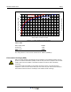


Table Of Contents
- Revision Record
- Table of Contents
- List of Figures
- List of Tables
- Abbreviations
- Chapter 1 Product Description
- Introduction
- Scope of Manual
- Safety
- Warning Signs
- Human Exposure of RF Radiation
- Radiation Safety Distances
- Electrostatic Discharge (ESD)
- Sub Unit Overview
- Wideband Amplifier PCBA (WBA)
- Power Amplifier PCBA (PA)
- Multi-Carrier Power Amplifier PCBA (MCPA)
- Booster Amplifier PCBA (BA)
- Distribution PCBA (DIA)
- Control Unit PCBA (CU)
- Low Noise Amplifier (LNA)
- Duplex Filter (DPX)
- Fiber Optic Unit (FOU)
- Fiber Optic Node (FON)
- Power Supply Unit (PSU)
- Remote Control Unit (RCU)
- Alarm Interface PCBA (ALI) and Remote Control Interface PCBA (RCI)
- Sub Unit Locations
- Fiber Optic Distribution Networks
- Multi-Operator Configurations
- Chapter 2 Controls, Indicators and Connectors
- Chapter 3 Installation
- Chapter 4 Maintenance
- Chapter 5 Specifications
- Appendix A Block Diagrams
Overview Wideband Radio Head
044-05251 Rev A 1-5
Overview
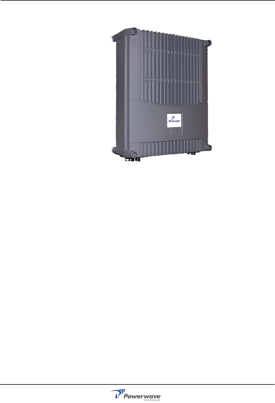
Figure 1-2 Powerwave Wideband Radio Head (WRH)
Powerwave WRHs work as bi-directional on-frequency amplifiers used to fill out uncovered
areas in wireless mobile systems such as base station fringe areas, tunnels, convention
centers, airports and business buildings. It receives, amplifies and transmits signals to/from a
base transceiver station (BTS) to/from mobile stations (MS) with both directions being served
simultaneously. Connections to the WRH are made with N-type or 7/16" male connectors.
WRHs are microprocessor controlled with alarm and operational status LEDs visible on the
front cover. Cooling is provided through convection heat dissapation.
Operational parameters, such as gain, channel number and power levels are set using a PC
running Powerwave OM-Online software which can communicate with the WRHs either locally
or remotely via modem. Remote operation can be performed via PSTN or a GSM net. The
Operation and Maintenance System (OMS) provides for Network Operations Center (NOC)
configuration and alarm monitoring.
WRHs can be configured in many combinations depending on the wireless system, single or
double system operation, and output power. The following paragraphs provide a description of
the different models of WRH’s available.
WRH
The Standard WRH is used for analog or digital systems such as GSM, TACS, ETACS, AMPS,
DAMPS, CDMA and WCDMA. It can be equipped with two bands in the cabinet and two bands
in a high cover. It has a fiber optic donor port and an RF port for a service antenna (or RF cable)
and is designed to be connected to a BTS via a BMU or OCM.
A booster option is available for the standard WRH to provide greater output power. This unit
is equipped with a 6dB Booster Amplifier (BA) in the downlink path. The BA reduces the
number of bands with one band per BA used in the cabinet and an additional one band if a high
cover is used. The BA is located in the cabinet and is supplied from the existing PSU. For two
bands, a high cover is used.