
User's Manual

DCM000000104 Rev Q
1-1
USU RF to Fiber
Remote Modules
These may be single or
multiple units, and are
usually grouped on floors
of a building, mounted in
Electrical Rooms.
In-Building
An te n n ae
Refer to Antenna
Installation Section
Head-End Module
Head-End Module
Head-End Module
Head-End Module
Head-End Module
HEAD-END DISTRIBUTION CENTER
REM OT E L OCAT I ONS IN BUI L DI NG
Any required
Amplifiers, Filters,
Couplers, Etc.
RF Cable
RF Cable
RF Cable
RF Cable
RF Cable
RF Cables
RF Cable
to/from
Base Station (s)
SMF = Single-Mode Optical Fiber
SMF
SMF
SMF
SMF
SMF
SM F
SM F
SM F
SM F
SM F
Chapter 1
Theory of Operation
1 Introduction
This manual contains information and procedures for installation, operation, and maintenance of
the LinkNet Uniserv Unit RF-FIBER Interface Modules. The manual is organized into the following
chapters:
Chapter 1 Theory of Operation Chapter 5 Operation
Chapter 2 Mounting Chapter 6 Antenna Installation
Chapter 3 Connections Chapter 7 Laser Safety
Chapter 4 Remote Module Chapter 8 Return for Service
1.1 Theory of Operation
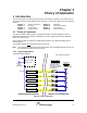
The USU RF to Fiber Modules provides a single-band link from a Headend distribution center to
multiple local antennae. RF signals are distributed over a pair of single mode fiber optic distribution
lines to each USU Remote.
Each Headend module can interface to multiple remote modules, the number depending upon the
Headend model.
The Headend modules do not
transmit directly out into the air.
Note! The remote module fiber optic I/O's are band specific, but the Headend fiber optic I/O's are not;
the Headend I/O's may be used for any band.
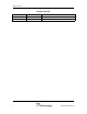
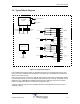
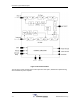
1.1.1 Typical Application
A typical installation would be....
Figure 1 Typical Application