
User's Manual
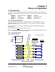
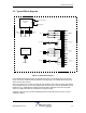
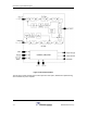

Table of Contents
iv DCM000000104 Rev Q
TABLE OF FIGURES
Figure 1 Typical Application ......................................................................................................... 1-1
Figure 2 Typical Block Diagram.................................................................................................... 1-3
Figure 3 US Remote Modules ......................................................................................................1-4
Figure 4 US Remote Modules Mounting ...................................................................................... 2-1
Figure 5 Power Supply Module and Mounting ............................................................................. 2-2
Figure 6 LNKFIB-H03/H04 Headend Module (Front)................................................................... 3-1
Figure 7 LNKFIB-H03/H04 Headend Module (Rear).................................................................... 3-1
Figure 8 LNKFIB-H03/H04 Headend Module Drawing (Rear) ..................................................... 3-1
Figure 9 US Remote Module Connections................................................................................... 3-2
Figure 10 ASY00420 DB15 Breakout Kit ..................................................................................... 3-3
Figure 11 Remote Module (Rear View)........................................................................................ 3-3
TABLE OF TABLES
Table 1 Available Models and Descriptions ................................................................................. 1-2
Table 2 Module Specifications...................................................................................................... 4-2
Table 3 Per-Carrier Derating ........................................................................................................ 4-3