
User's Manual


Configuration and PC Commands
5-2
DCM000000104 Rev Q
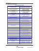
Remote Modules:
ACCESS USER: Required as a simple password to gain access to customer settable
parameters and diagnostics; This will time-out after 10 minutes, and may
have to be re-typed.
HELP or ?: Displays a list of Available Commands.
LIST: Displays Current Settings and Status Faults, Etc.
VER: Display the current Version of Software.
ENABLE 1 or 0: Enables or Disables the Module.
DLGATTN ###: Displays or Sets the Downlink Gain Reduction, which is in tenths of a dB.
Please consult Powerwave Technologies Inc. for further support.
5.2 Gain Adjustments
Gain adjustment is necessary to compensate for the variations in the fiber optic components of the
Headend and Remote modules. This must be done after modules are deployed in a system, and
anytime a module is replaced. The adjustments are on an individual RF path basis, and each path is
adjustable downwards in 1dB steps up to -15dB.
It is recommended that these adjustments be performed with the aid of a Signal Generator and
Spectrum Analyzer.
Uplink Gain:
The uplink gain is adjusted at the Headend module on an individual RF path basis. Please refer to the
Headend DIGATTN commands in the Configuration and PC Commands section. All DIGATTN
values are set to 0 (Maximum RF Gain). While monitoring the RF gain via measurements, the
individual gain paths are adjusted downwards with the DIGATTN command to meet the specified gain.
This will optimize/balance both gain and noise.
Downlink Gain:
The downlink gain is adjusted at the remote module an individual RF path basis. Please refer to the
remote DLGATTN commands in the Configuration and PC Commands section. All DIGATTN values
are set to 0 (Maximum RF Gain). While monitoring the RF gain via measurements, the individual gain
paths are adjusted downwards with the DLGATTN command to meet the specified gain. This will
optimize/balance both gain and noise.
5.3 Signal Level Adjustments
Signal level adjustment is necessary to ensure that the downlink RF carriers transmitted via the remote
modules are not generating undesired intermodulation products, nor are they being distorted beyond
use. Refer to the earlier section on Remote Module Per-Carrier Derating.
It is recommended that these adjustments be performed with the aid of a Signal Generator and
Spectrum Analyzer, and that they be done AFTER the gain adjustments.
Adjust the downlink interface amplifiers and/or attenuators between the base stations and the Headend
modules (see the Typical Application drawing) to achieve the specified derated per-carrier level.
Uplink signals should be monitored as they feed into the base station, this is usually a site specific
requirement.