
User's Manual


DCM000000104 Rev Q
5-1
Chapter 5
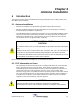
Operation
5 Introduction
This chapter contains operational and standard safety information for the LinkNet Uniserv Unit
RF-FIBER Interface Modules.
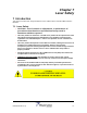
5.1 Operation
Normal operation for both USU Headend and Remote modules:
•
POWER / OPERATING - GREEN when the module is operating.
•
FAULT – Red if the internal diagnostics detect a problem.
•
LASERS ON - GREEN when any one of the lasers are operating.
5.1.1 Fault Indications
Each module continuously performs internal diagnostics. If a problem is detected it will activate its
Red Fault LED and Fault Relay. Faults detected include;
• Over Temperature.
• Misc. Internal Faults.
Detailed faults are detected by the optional Gateway Module. Details may also be determined via
an RS232 connected Terminal Emulator using the LIST command.
5.1.2 Configuration and PC Commands
It is possible to re-configure modules in the field, either with a personal computer (PC) or via the
optional LinkNet Gateway Module. To use a PC it is necessary to connect the DB9 RS-232/USB
connector on the module to a standard DB9 RS232/USB connector on the PC. On the PC a
terminal emulation program such as
HyperTerminal
is used to communicate to the LinkNet
module. The settings are 9600 baud, 8 bits, no parity, and 1 stop bit. Commands are one or two
words followed by pressing Return. Commands may be given in upper or lower-case. Available
commands are listed below for each module.
Headend Modules:
ACCESS USER: Required as a simple password to gain access to customer settable
parameters and diagnostics; This times-out after 10 minutes, and may
have to be retyped.
HELP or ?: Displays a list of Available Commands.
LIST: Displays Current Settings and Status Faults, Etc.
VER: Display the current Version of Software.
ENABLE 1 or 0: Enables or Disables the Module.
DIGATTN x yyy: Displays or Sets the Uplink Gain Reduction yyy, which is in tenths of a
dB. The Optical to RF Path being set is x, which is;
x = 0 is for Uplink Optical to RF Path A1
x = 1 is for Uplink Optical to RF Path A2
x = 2 is for Uplink Optical to RF Path A3
x = 3 is for Uplink Optical to RF Path A4
x = 4 is for Uplink Optical to RF Path B1
x = 5 is for Uplink Optical to RF Path B2
x = 6 is for Uplink Optical to RF Path B3
x = 7 is for Uplink Optical to RF Path B4