
User's Manual

Module Specifications
4-2
DCM000000104 Rev Q
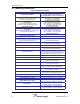
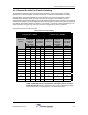
4.3 Module Specifications
Table 2 Module Specifications
Frequency Bands
Refer to Model Chart
Maximum Downlink Power
+38 dBm IP3 Min. iDEN/Cell/Page/GSM900/700PS
+36 dBm IP3 Min. for PCS, GSM1800
(see Remote Module Carrier De-Rating Chart)
Maximum Uplink Power
Combined at any Headend RF Output.
Includes the 4-way combiner loss.
+4 dBm IP3 Min., iDEN/Cell/Page/GSM900/700PS
0 dBm IP3 Min., PCS/GSM1800
(7 to 12dB higher for LNKFIB-H01)
Downlink Gain
from Headend to the Remote Module
Antenna Port, assuming 0dB Fiber-Optic Link
+20 dB after Gain Adjustment
Typical range before Gain Adjust is
+20 to +35 dB for 700-900 MHz Bands
+20 to +31dB for 1.8-1.9 GHz Bands
(See Gain Adjustments)
Downlink Gain Ripple
+/- 3.5 dB over entire Band
Uplink Gain
from Remote Module Antenna Port to Headend,
assuming 0dB Fiber Optic Link
+20 dB after Gain Adjustment
Typical range before Gain Adjust is
+20 to +32 dB for 700-900 MHz Bands
+20 to +32dB for 1.8-1.9 GHz Bands
(See Gain Adjustments)
Uplink Gain Ripple
+/- 3.5 dB over entire Band
Max RF Input without Damage
To Headend Units
+10 dBm
Uplink Noise
at Headend Unit from any Remote Module Antenna
Port assuming 0dB Fiber Optic Link
< -130 dBm/Hz
(with Uplink Gains Balanced)
Isolation
Consult Powerwave Engineering Services
(depends upon Headend Filtering)
Duty Cycle
Continuous
Spurious Outputs
-20 dBm max per Remote Module Antenna Port
when operated as per Derating Chart
Optical Power Level
Laser Warning:
Invisible Laser Radiation emitting
from optical connector. Avoid direct exposure to
beam. 150 mW max. @1300nm. Class IIIb. Product
complies with 21 CFR 1040.10 and 1040.11.
Optical Path Loss
2 dBO Maximum
Group Delay
<2uS,
NOT
including Fiber Optic Link
Connectors
SC/APC Fiber Optic, SMA (50Ω) RF
D-Sub, USB, Data & Control
Headend Module Power Supply Requirements
120/240 VAC, 50/60 Hz,
75 VA Typical, 90 VA Max.
Remote Module Power Supply Requirements
28 VDC from external Power Supply, 0.75A Max
and 24VDC "Gell-Cell" Battery Backup Option
US-PS01 Power Supply Requirements
120/240 VAC, 50/60 Hz,
30 VA Typical, 70 VA Max.
Configuration Options
Either via the USU network and a Gateway Module,
or via a PC and an RS-232/USB Connection.
Operating Temperature Range
-20 to +50
o
C
Operating Humidity Range
5 to 90% RH, Non-Condensing
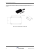
Headend Module Size & Weight
1U High 19” Rack Unit, 14" Deep, 16 lbs Max
Remote Module Size & Weight
2.75” High, 9.25” Wide, 11” Deep, 6 lbs Max
70mm(H), 235mm(W), 280mm(D), 2.7Kg Max.
FCC Identifiers
FCC: H6M-US800TP FCC: H6M-US800C
FCC: H6M-US900P FCC: H6M-US1900P
Industry Canada Certifications
IC: 1541A-US800TP IC: 1541A-US800C
IC: 1541A-US900P IC: 1541A-US1900P