
User's Manual
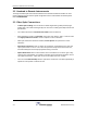


Headend to Remote Interconnections
3-4 DCM000000104 Rev Q
3.2 Headend to Remote Interconnects
The single mode fiber optic interconnections between the Headend and Remote modules are to be
made in whatever manner suits the system configuration. For the CAN Network connections please
refer to DCM000000103.
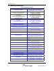
3.3 Fiber Optic Connections
• All Fiber Optic Cabling must use 9/125 or similar Single-Mode (yellow jacketed) high-
quality cable. This cable should typically have less than 0.5 dBo (optical dB) insertion loss
per kilometer.
• The cable manufacturer's
minimum bend radius
must be observed.
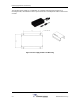
• Most Powerwave products use SC/APC connectors. Note that the "APC" is critical. These
are
angle-polished connectors
and are required to reduce reflections.
• Fiber-Optic Patchcords should be avoided;
Fusion-Splices
are preferred to reduce
reflections.
• Fiber-Optic Connectors, both on cables and equipment, should always have their dust
caps in place when not in use. The connector tips must be kept clean and scratch free,
and should always be cleaned properly before being connected.
• Optical Reflections back into laser diodes cause a disturbance in the lasers gain cavity
creating noise and distortion. An OTDR or other fiber optic instruments should be used to
check optical reflections. Fiber optic return loss should be less than -50 dBo.
• There is a 2 to 1 Relationship between optical loss and RF loss. One dBo (optical dB) of
optical loss corresponds to 2 dB of RF loss.