
User's Manual

US Remote Module Connections
3-2
DCM000000104 Rev Q
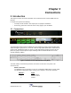
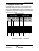
User I/O Connection:
This Connection is via a standard 15-pin female D-Sub connector on the side of the
enclosure...
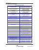
DB15 Pin #
Signal
1 CAN High
9 CAN Low
8 CAN Common (Ground)
3 Fault Relay Common
2 Fault Relay - Closed for Fault
4 Fault Relay - Open for Fault
The Form-C Relay is rated at 30 VDC @ 1 Amp or 30 VAC @ 0.5 Amp.
Refer to the DCM000000103 CAN Wiring Guide.
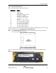
3.1.1 US Remote Module Connections
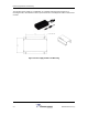
Figure 9 US Remote Module Connections
The Remote Module has 1 or 2 SMA RF connections..
RF Xcvr: For the normal (non -2) models there is a single RF transceiver port
used to connect to a distributed indoor antenna system.
RF Tx & Rx: For the 2-Port (-2) models there are RF transmit and receive ports
used to connect to external filtering and combining, then to a
distributed indoor antenna system. Consult Powerwave for details.
Fiber-Optic Ports: There are two SC/APC single mode fiber optic connections for cabling
to the Headend.
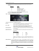
RS232 Connection: There is a RS232 connection via standard 9-pin female D-Sub connector.
It is wired as;
DB9 Pin #
Signal
1 DCD in 6 DSR
2 Transmit 7 CTS in
3 Receive 8 RTS out
5 Ground 9 RI in
RS232 is for interfacing to a PC via a straight-through DB9 male to
female cable, and operates at 9600 baud, 8 bits, no parity, and 1 stop
bit.
USB Connection: To use the USB port on the USU, a virtual COM port driver must first be
installed using the driver CD-ROM shipped with the USU. This virtual COM
port driver will create a new COM port that will use the next available port
number. For example, if your PC has two COM ports, the virtual COM port
driver will create a COM3 port. Follow the instructions on the CD to install the
driver.