
User's Manual


DCM000000104 Rev Q
3-1
Chapter 3
Connections
3 Introduction
This chapter contains connection information for the LinkNet Uniserv Unit RF-FIBER Interface
Modules.
It is important to perform the following:
• Carefully read all material in this chapter prior to equipment installation.
• Review any government and local codes as they apply to your installation.
3.1 Connections
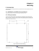
Figure 6 LNKFIB-H03 Headend Module (Front)
Figure 7 LNKFIB-H03 Headend Module (Rear)
The LNKFIB-H03 Headend has two downlink RF Inputs providing the signal for eight downlink optical
outputs arranged as groups of four, "A" and "B". It also has eight uplink optical inputs, combined in two
groups of four, providing RF outputs "A" and "B". The RF and optical connections are all on the rear
panel. The group of four RF input and output combining inside the module alleviates the need for
external combining / splitting.
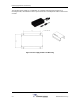
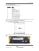
Figure 8 LNKFIB-H03 Headend Module Drawing (Rear)
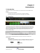
The CAN, RS232, and Fault Relay Interface connections are all on the front panel. Their
connections are;
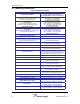
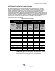
RS232 Connection:
The RS232 Port is for interfacing to a PC via a Null-Modem DB9 female to female cable,
and operates at 9600 baud, 8 bits, no parity, and 1 stop bit. It is a 3-wire connection.
DB9 Pin #
Signal
2 RS232 Receive
3 RS232 Transmit
5 Ground