
User's Manual


Functional Description
1-4 044-05210 Rev. A
1.3.5 Operational States
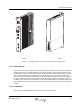
The IPT has three operational states: Operational, Disabled and Not Ready.
The IPT remains in the Not Ready state during start-up until all parameters are met for the IPT to
become operational.
The IPT is normally in the Operational state: no faults are present, the IPT internal temperature is
within limits, appropriate DC power is applied, and the IPT is producing RF output. The green
operational (O) LED on the Man Machine Interface is lit.
The Disabled state is ordered from the RBS (if there is a fault in the IPT or in other RBS units) or
entered automatically when a critical hardware error is detected by the IPT. The Disabled state
causes the IPT to shut down, but it can be enabled by the RBS if the fault is cleared.
1.3.6 State Transitions
The IPT has five state transitions: Reset, Status OK, Alarm, Disable, and Enable.
Reset initiates the Not Ready state. This state is entered when power is initially applied to the IPT or
from a dedicated reset signal from the RBS to the IPT.
Status OK is entered from the Not Ready state and initiates the Operational state when commanded
by the IPT
Alarm initiates the Disabled state from the Operational state if the IPT detects a hardware or
temperature fault. The RBS reads the potential fault cause for fault logging.
Disable is ordered from the RBS to force the IPT to go to the Disabled state and shut down. Power on
of the IPT after a Disable can only be ordered by the RBS through a RESET command.
Enable is ordered from the RBS to power on the IPT after it has been disabled. The IPT enters the
Operational state after checking status and temperatures and re-perform start-up if required.
1.3.7 DC Power (DC)
DC power (-48 Vdc nominal) is supplied by the RBS to the IPT through the rear mounted connector.
Refer to
Table 1-1 for a description of the DC connector inputs.
1.3.7.1 Power Supply
The power supply assembly contains two subassemblies. The DC/DC converter produces regulated
+28 Vdc, +9 Vdc and +6.5 Vdc from the -48 Vdc supply for the IPT internal supply. The low voltage
supply uses the +6.5 Vdc from the DC/DC converter to provide regulated 3.3 Vdc, 1.8 Vdc and 1.5
Vdc reference level supplies.
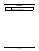
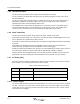
Table 1-1 DC Power Connections
Pins Signal Name Description
1,2 GND (-48V_RTN) DC plus (isolated from amplifier chassis)
3,4 -48V DC minus (isolated from amplifier chassis)
5,6 GND (NC) Not connected