
User's Manual


Initial Start-Up and Operating Procedures
3-2 044-05205 Rev. A
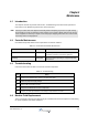
3.2.2 Status and Alarm Indicators
MCPA alarm conditions are reported to the system as logic level signals through the rear connector.
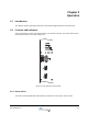
The front panel LED provides a visual reference for the operator of MCPA status. Refer to
Table 3-1.
The IPT ALARM (INT.) lights when a IPT fault occurs. The IPT control logic provides the following
alarms to the RBS when a fault occurs:
• Temperature out of range
• Voltage out of range
• Current out of range
• Open circuit (reported as a voltage out or range alarm)
• Short circuit (reported as a current out of range alarm)
• Hardware fault. A hardware fault always requires removal and replacement of the IPT to resolve
the fault condition.
Some MCPA alarms are caused by faults external to the IPT such as an out of tolerance DC supply or
RF supply. A major fault will disable the RF output of the IPT, a minor fault has no effect on the RF
output. Conditions external to the IPT should be investigated before replacing the IPT.
3.3 Initial Start-Up and Operating Procedures
No operator action is required during start-up and normal operations: the IPT powers up when -48
Vdc power is applied, the IPT internal temperature is within operating range, no faults are present, RF
input and output are within specifications and the IPT is commanded to power up by the RBS logic. If
the IPT does not power up or the ALARM (INT.) LED stays lit, refer to Paragraph
4.3 for
troubleshooting instructions.
CAUTION: Before applying power, ensure the input and output of the system is properly
terminated at 50 ohms. Do not operate the system without a load attached. Refer to
Chapter
5 for input power requirements, excessive input power may damage the IPT.