
User's Manual


Fiber Optics Powerwave
7 - 6 Rev. P1A9-Draft 2004-11 VM100 56/EN – User’s Manual
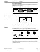
Fiber Optic Cables
Fiber optic 9/125µm single-mode patch cables for Powerwave repeaters are normally
delivered with the system.
Recommended backbone cables: Single-mode 9/125µm fiber optic cables.
Single-mode 9/125µm fiber optic cables have a very good bandwidth-distance product
and a low cable loss, see below.
To add cable length, permanent splices are generally used outside buildings while
connectors are generally used inside buildings. Permanent slices are described below,
connectors are described in the next section.
Bandwidth-distance product
The bandwidth-distance product (MHz km) for this cable type is higher than 20,000
for both 1310nm and 1550nm. As a comparison, a 50/125µm multi-mode cable has a
product between 300 and 1,500.
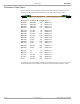
Cable loss
The cable loss is found in the following table.
Additional loss for optical connectors is approximately 0.5dB per connector.
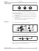
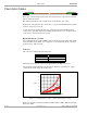
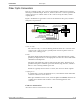
The following diagram illustrates the attenuation differences between some copper
coaxial cables and the single-mode fiber cable.
Figure 7-9. Attenuation for copper coaxial cables and fiber cable
Figure 7-9 shows the attenuation for RG-58, RG-62, RG-11, RG-8, RG-6U and single-
mode fiber (SM).
Wavelength Loss
1310nm 0.35dB per kilometer.
1550nm 0.20dB per kilometer.
0
600
1
700 MHz
500
400
300
200
100
10 50 100 200 400
dB/km
RG-58
RG-62
RG-11,
RG-6U
RG-8
SM