
User's Manual

Fiber Optics Powerwave
6 - 10 Rev. P1A9-Draft 2004-11 VM100 56/EN – User’s Manual
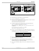
Legend:
Fixed values.
Set values via O&M software.
Calculated or resultant values.
Set and resultant UL gain
values in red.
High, medium, and low values
in the example.
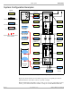
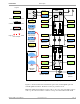
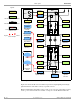
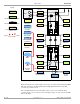
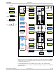
Figure 6-8. Nine FORs, low optical loss, high uplink gain and attenuation
Figure 6-8 shows one of nine FORs connected to one of three FON units in the BMU
with low optical loss, high uplink gain and high uplink attenuation. The BTS sensitivity
degradation is high.
High total uplink gain and a BTS sensitivty with repeater very close to the BTS sensitivity
at the repeater antenna indicates a similar coverage area for the BTS and the FOR.
0dB
0dB
0dB
0dB
FON
BTS
BMU
DL
UL
FON
FOR
1 1
DPX
TX level
Total UL gain
RX Att. TX Att.
Fiber/WDM/
splitter loss
TX Att. RX Att.
UL gain
DL gain
Repeater noise figure
BTS sensitivity at
repeater antenna
Limited
repeater
TX level
Total DL gain
BTS initial
noise figure
BTS initial
sensitivity
BTS sensitivity
with repeater
BTS sensitivity
degradiation
Number of
repeaters
Fiber/WDM/
splitter loss
Coverage
areas
BTS
FOR
20dB
0dB
20dB
0dB
0dB
40dBm
5dB
–107dBm
15.3dB
9
1.5dBm1.5dBm
1.5dBm 1.5dBm
10dB
20dB
55dB 68dB
–91.8dBm 33dBm
–7dB
5dB
10dB 20dB
–91.7dBm