
User's Manual

Powerwave Fiber Optics
VM100 56/EN – User’s Manual Rev. P1A9-Draft 2004-11 6 - 5
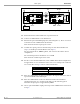
18. Move the O&M software back to the repeater and set uplink attenuation and gain.
Example of downlink and uplink settings are found in the following table.
The optical system is now ready for operation. A fine-tuning of the system should be
done to get the most out of the system. And, the more nodes in the system the more
reason to balance and fine-tune it.
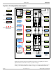
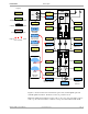
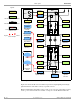
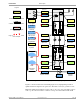
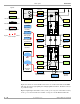
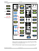
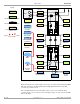
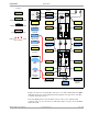
The following section contains some system configuration examples.
Unit Downlink Uplink
BMU (FON) 5dB att. 10dB att.
FOR (FON) 10dB att. 5dB att.
BMU (RF) 60dB gain 60dB gain