
User's Manual

Powerwave Fiber Optics
VM100 56/EN – User’s Manual Rev. P1A9-Draft 2004-11 4 - 11
Noise, Intermodulation and Dynamic Signal Range
This section contains brief descriptions of noise, intermodulation, and dynamic signal
range.
Noise and intermodulation
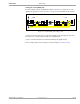
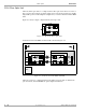
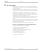
Figure 4-9 shows noise and intermodulation values for the optical transmission.
Figure 4-9. Noise and intermodulation
If the fiber loss, L
FO
, is lower than 5dB, the output noise figure, NF
OUT
, is determined
by the optical transmitter (’1’ in Figure 4-9).
If the fiber loss, L
FO
, is higher than 5dB, the output noise figure, NF
OUT
, is determined
by the receiver amplifier (2).
Intermodulation and IP
3
The third order of intermodulation is illustrated on a frequency axis in the figure.
The formula for it reads: IM
3
= 3P
0
– 2IP
3
dB
where:
IM
3
= Intermodulation level.
P
0
= Carrier power.
IP
3
=The IP
3
point of the amplifier.
The IP
3
values from the various types of repeater amplifiers are:
BSA 54dBm
CHA 68dBm for 2 channels, 65dBm for 4 channels.
ALR 48dBm (compact repeater and RH)
WRH 35dBm
Dynamic signal range
The dynamic range for the RF signal is determined by the noise level and the IM
requirements. The dynamic range is represented by a vertical arrow in the figure, where:
P=Power
S=Signal level.
N = Noise floor + intermodulation.
FON
1
RX
L
FO
FON
NF = 3 – 4dB
TX
NF
=
30 – 35dB
IP
3
= 30 – 35dBm
NF
OUT
1
2
Gain 30dBConversion loss 25dB
2f
1
–f
2
f
1
f
2
2f
2
–f
1
D
P
X
P
S
N