
User's Manual

Fiber Optics Powerwave
4 - 2 Rev. P1A9-Draft 2004-11 VM100 56/EN – User’s Manual
The RF Modulated Signal Paths
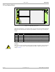
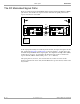
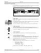
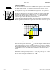
Figure 4-1 illustrates the downlink RF modulated signal path from the BTS via a BMU,
optical fiber, and a FOR to the repeater antenna. And also the uplink path from the
repeater antenna back to the BTS.
Figure 4-1. Downlink and uplink RF modulated signal paths
As the signal paths mainly are handled by the FON units, the signal description for this
unit, found in the RF Path 1 and RF Path 2 sections in Chapter 3, is applicable to the
downlink and uplink RF modulated signal paths. The amplifiers and duplex filter (DPX)
in the FOR are, however, not included in the FON description, but are found in the
repeater manual (VD203 66/EN, AR Repeaters, User’s Manual).
The signal paths are, however, also described below, but more in terms of radio
frequency signals in the entire chain, from the BTS to the repeater antenna, and the other
way around.
BTS
FON
BMU
FON
FOR
D
P
X
DC
1
TX
RX
1
TX RX
D
P
X
UL
DL