
User's Manual


Powerwave Fiber Optics
VM100 56/EN – User’s Manual Rev. P1A9-Draft 2004-11 7 - 9
Fiber Optic Connectors
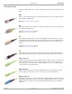
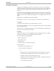
There are a number of fiber optic connector types that have different charactersistics,
advantages, and disadvantages. There are, however, three basic connector parts that all
of these types have in common. These are the connector body, the ferrule, and the
coupling device.
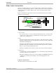
Figure 7-10 illustrates a typical fiber connector in which these three parts, and other
main parts, are pointed out.
Figure 7-10. Typical fiber optic connector
Connector body
The connector body, or connector housing, holds the ferrule in a center line of the
connector. The connector body is generally made of metal or plastic and it can
consist of one or many pieces.
Ferrule
The ferrule holds and align the fiber. The ferrule is, when inserted in the coupler,
guided by an alignment sleeve to the right position to meet the connected fiber with
a minimum of misalignment.
The ferrule end and the fiber end are aligned in the same plane. The fiber face is
polished in this plane to minimize power loss. Hackles, lips, fractures, and dirt at
this face cause scattering and thus power loss.
Ferrules are typically made of metal or ceramic, but can also be made of plastic.
Coupling device
A coupling device, such as an alignment sleeve, is used instead of male and female
connectors common to electric devices.
Fiber optic transmitters and receivers, as well as splitters and WDMs, often have the
coupling devices built-in and can thus be connected with applicable cable
connectors.
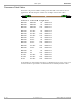
Connector insertion loss
All connectors have an insertion loss of 0.5dB.
Fiber cable
Bend relief boot
Coupling device
Alignment sleeve
Crimp ferrule
Retaining ring
Connector body
Knurled coupling nut
Ferrule