
User's Manual


Powerwave Fiber Optics
VM100 56/EN – User’s Manual Rev. P1A9-Draft 2004-11 7 - 3
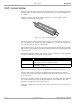
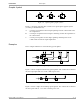
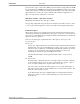
Graphic Symbol
Figure 7-2. Optical splitter graphic symbol
Figure 7-2 shows the following three variants of an optical splitter graphic symbol
(according to the EIA/TIA-587):
A – A 50/50 percent splitter used for simplex splitting, from the common fiber to the
two output fibers.
B – A 30/70 percent splitter used for simplex combining, from the two input fibers to
the common fiber.
C – A 30/70 percent splitter used for duplex splitting/combining between the
common fiber and the two input/output fibers.
Examples
These examples illustrate two networks using optical splitters.
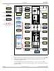
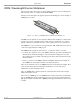
Figure 7-3. Optical splitters in a simplex network
Figure 7-3 shows a simplex network using optical splitters. The common fiber is divided
into four output parts with 25% of the common power each.
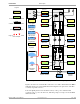
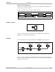
Figure 7-4. Optical splitters in a duplex network
Figure 7-4 shows a duplex network using optical splitters. The common fiber is divided
into three parts with 30 – 35% of the common power each.
A
B
C
50
50
30
70
70
30
1
1
50
50
50
50
50
50
50
50
50
50
50
50
1
30
70
50
50