
User's Manual

Fiber Optics Powerwave
6 - 2 Rev. P1A9-Draft 2004-11 VM100 56/EN – User’s Manual
Commissioning the Fiber Optic System
Commission the optical transmission system as described in the following instruction.
The instruction covers the optical system only and is therefore applicable to all units
with optical transmission, for instance BMU, RMU, OCM, FOR, and RH.
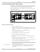
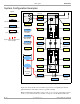
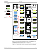
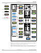
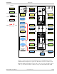
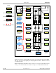
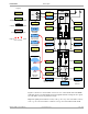
Figure 6-1 shows a fiber optic system in a BMU and a FOR. These units are also used
as examples in the instruction.
Figure 6-1. Master unit downlink path
Master Unit Downlink Path
1. Make sure the BMU is switched off.
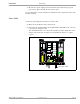
2. Measure the downlink input RF signal power (from the BTS) at the FON board
connector ’P101’ in Figure 6-1 (or at the OCM/BMU 19" rack) using a spectrum
analyzer.
The signal power should be between +10dBm and +36dBm.
Write down the measured power value.
3. Switch the BMU on and wait until it is in operational mode.
4. Connect the O&M software to the FON board.
5. Measure the optical output power from the FON board (TX) using an optical
power meter.
If there is only one slave unit on a short distance, choose the low power range.
Otherwise, keep the default high power range.
If you are in doubt, choose high power and, if needed, change to low power if the
received optical power is more than 4dBm at the slave unit.
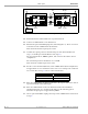
6. Set the transmitter attenuation (TX Att.) to a value that gives the following optical
transmitter an input power of approximately 0dBm. The attenuation is set via the
O&M software (FON configuration).
P
P101
– 20dB – XdB = 0dB Meassured RF input signal level at P101 minus 20dB minus XdB attenuation
equals 0dB. X is the attenuation set via O&M software. Write down the
attenuation set.
BTS
BMU
FON
DC
FON
FOR
P101
TX Att.
0dBm
TX
1
TX
RX
1
TX RX
D
P
X
UL
DL
D
P
X