
User's Manual


Fiber Optics Powerwave
5 - 6 Rev. P1A9-Draft 2004-11 VM100 56/EN – User’s Manual
The FON Unit Net Interfaces
This section describes the FON unit in networks, one of the most important subunits in
repeater networks. The FON unit is here described as a block with network interfaces.
The FON board contains all software and protocols required for both W-net and F-net
communication, routing included. A sole FON board can be a complete node in an F-net
or W-net.
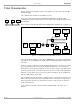
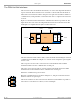
Figure 5-5 shows the FON board with the communication interfaces pointed out. The
figure shows also some of the most important function blocks on the FON board. The
small figure is a simplified block symbol of the FON board.
Figure 5-5. FON with communication interfaces
The CPU unit with loaded software (SW) controls the FON unit including the network
communication. The RF block in Figure 5-5 converts electrical signals to optical signals
and vice versa.
The local port is used for cable connection between the FON unit and an O&M
workstation. PPP is used for communication via this port.
The remote port is used for remote connection between the FON unit and an O&M
workstation via modem. PPP is used for communication via this port.
WLI is the communication port for W-net.
FLI is the communication port for F-net. In Figure 5-5, this part of the FON board is
marked to indicate an optical part.
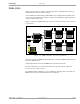
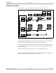
The W-net and F-net are interconnected in the FON board, which makes it possible to
interconnect several F-nets via a W-net, see the small figure.
FON
FLI
RX
TX
WLI RF
CPU
SW
FON
FO
FO
FO
Local Remote
W-net F-net
FON
FON
FON
FO
FO
FO