
User's Manual

Fiber Optics Powerwave
4 - 8 Rev. P1A9-Draft 2004-11 VM100 56/EN – User’s Manual
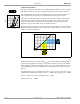
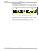
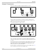
Uplink RF Signal Path
The uplink RF modulated signal path, from the repeater service antenna to the BTS, is
shown in Figure 4-5. The item numbers in the figure are described below. Item numbers
are omitted for those items that have the same function and settings as in the downlink
path.
Figure 4-5. Uplink RF transmission path
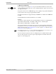
1. Repeater amplifier
The repeater amplifier is the same as the downlink amplifier, but in this case the output
power should be adjusted to match the FON input power range, 10 – 36dBm.
2. Power attenuator
The input 16dB/8W power attenuator is the same as the downlink amplifier, but in this
case an alternative configuration can be used.
In the alternative configuration a FON unit without this power attenuator is used. In this
case a lower output power from the FOR unit is fed directly to the following adjustable
attenuator.
The advantage of this configuration is less signal noise.
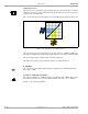
3. Software adjustable attenuator
The software adjustable 0 – 20dB attenuator is set manually via an O&M software. This
is described in the FON section of the VM100 01/EN, OM-Online, User’s Manual.
If the BTS has a larger coverage area than the repeater, then the attenuator is usually
adjusted to a total uplink gain to the BTS of –10dB (shown in the figure).
If the coverage area is the same for the BTS and the repeater, then the BTS antenna input
sensitivity with connected repeater should be the same as the sensitivity at the repeater
antenna input.
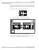
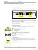
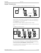
The total uplink gain can, however, not be set only on the software adjustable attenuator
but has to be balanced on the three uplink set points highlighted in Figure 4-6 (see the
next section).
FON
FON
DC
D
P
X
1
TX
RX
312
D
P
X
UL
FOR
BMU
16dB, 8W
D
P
X
0 – 20dB
D
P
X
DC
BMU
FON
BTS
–10dB