
User's Manual

Powerwave Fiber Optics
VM100 56/EN – User’s Manual Rev. P1A9-Draft 2004-11 4 - 3
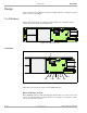
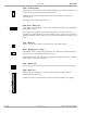
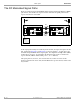
Downlink RF Signal Path
The downlink RF modulated signal path, from the BTS to the repeater antenna, is shown
in Figure 4-2. The item numbers in the figure are described below.
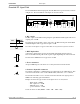
Figure 4-2. Downlink RF transmission path
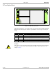
1. DC coupler
The DC coupler on the BTS antenna path picks up the BTS downlink signal with a fixed
coupling loss of 20dB.
The left figure shows the DC coupler connected to the BTS antenna path and the BTS
downlink amplifier with a typical noise figure of 5dB.
The values in the figure are typical values that can vary from one system to another.
2. DPX duplex filter
A Powerwave duplex filter separates the downlink and uplink signal frequencies
between the BTS antenna path and the separate input/output RF ports of the FON unit.
The Powerwave DPX filter has a typical loss of 1dB.
3. Power attenuator
An input 16dB/8W power attenuator is a security attenuator for the FON unit.
4. Software adjustable attenuator
The software adjustable 0 – 20dB attenuator is set manually via an O&M software. This
is described in the FON section of the VM100 01/EN, OM-Online, User’s Manual.
The attenuator should be set to a calculated value that attenuates the signal power to
0dBm to the following optical transmitter.
Example: Presume the typical values in the figures above are used, that is:
– BTS output = 40dBm
– DC coupler loss = 20dB
– DPX filter loss = 1dB
– power attenuator = 16dB
Set the attenuator to 3dB (40dBm – 20dB – 1dB – 16dB = 3dB).
BMU
FOR
DC
1
TX RX
2 3 4 5 6 7 8 9 10 11
12
1
FON
FON
DL
D
P
X
D
P
X
NF 5dB
40dBm
20dB
BTS
BMU
DL
DC
D
P
X
16dB, 8W
0 – 20dB