
User's Manual

Fiber Optics Powerwave
3 - 6 Rev. P1A9-Draft 2004-11 VM100 56/EN – User’s Manual
Design
This section describes the FON board layout, including indicators, coaxial ports, optical
ports, connectors, and jumpers.
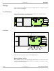
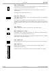
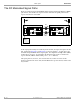
The FON Board
The FON board is built up on a printed circuit board that also contains the battery
backup. The FON board is shown in Figure 3-4.
Figure 3-4. The FON board
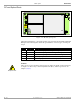
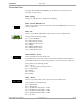
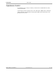
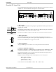
Indicators
Figure 3-5. FON indicators and ports
The FON board contains the below described LED indicators.
FLI (or F2F) fiber network
Green LED that indicates, with a flashing light, that the unit receives data over the sub
carrier. A steady light indicates that the unit does not currently receive any data, or there
is no other node in the network.
P102
P130
Bery llium
oxide
hazard
P103
P101
P114
P108P116P111
P105P109P115
P106
P104
RX
TX
P113
P112
P110
OPER
FAULT
POWER
BOOT
P130
P114
P108P116P111
P105P109P115
P106
P104
RX
TX
P113
P112
P110
WLI/R2R
DATA
BATT
CHARGE
FLI