
User's Manual

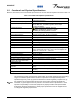
Table Of Contents

044-05117
Chapter 1 General Description
1-1 Introduction
This manual contains information and procedures for installation and servicing of Powerwave’s G3L-850-135
Amplifier. The manual is organized into two chapters as follows:
Chapter 1 General Description Chapter 4 Principles of Operation
Chapter 2 Installation Chapter 5 Maintenance
Chapter 3 Operating Instruction Appendix A Glossary of Terms
1-2 General Description
The G3L-850-135 Power Amplifier, shown in Figure 1-1 - Figure 1-5, operates in the 25 MHz frequency band
from 869 MHz to 894 MHz with an instantaneous bandwidth of less than 25 MHz. The instantaneous
bandwidth is the maximum frequency band in which any two or more signals can occupy .The amplifier’s
instantaneous bandwidth is set automatically and does not require any manual setup. The amplifier is
modular in design. Table 1-1 gives additional essential operating specifications.
Table 1-1. General Operating Parameters
Characteristic Performance Remarks
Operating Frequency Band 869 MHz to 894 MHz
Instantaneous Bandwidth 25MHz
Gain 63 dB
Spurious Performance ITU-R SM329-9, Category A Non-carrier related
Receive Band Noise -98 dBm/Hz In RX channels associated with RF
input terminated into 50 Ω.
Supply Voltage 21 Vdc to 30 Vdc Nominal +27 Vdc. Degraded mode of
operation at less than 26 Vdc.
Heat Output 3,074 BTU At full rated power
Carrier Types
GSM (up to 12 carriers) or
EDGE +GSM (up to 4 carriers for
each)
WCDMA (up to 4 carriers)
GSM 11.21
TS 25.141
3GPP2 C.S0010-B
Storage Temperature -40 - +85 °C
Ambient Temperature -33 - + 50 °C
Altitude -50 - +4,000 m
Installation and Service Manual - G3L-850-135 Multi-Carrier Power Amplifier 1-1