
User's Manual


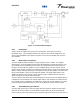
Table Of Contents

044-05117
loop fault occurs. When this happens, an alarm indicator is illuminated on the front panel of the
subrack. The fault is transmitted back to an external summary module via the external alarm
interface connection on the front panel of the subrack.
4-4.4 First and Second Loop Control Circuits
The primary function of the first loop is to amplify the carrier signals and isolate an error signal for
the second loop. The primary function of the second loop is to amplify the error signal to cancel
out spurious products developed in the main amplifier. The input signal is amplified by a
preamplifier and fed to a coupler and delay line. The signal from the coupler is fed to the
attenuator and phase shifter in the first loop. The first loop control section phase shifts the main
input signals by 180 degrees and constantly monitors the output for correct phase and gain.
The second loop control section obtains a sample of the distortion added to the output signals by
the main amplifiers. The signal is phase shifted 180 degrees, then fed to the error amplifier where
it is amplified to the same power level as the input sample. The signal is then coupled to the error
signal of the main amplifier output. The final output is monitored by the second loop and adjusted
to ensure that the signal distortion and intermodulation distortion (IMD) on the final output is
cancelled out.
4-4.5 Pilot Tone Generator
A Pilot Tone is an internally generated signal, who’s precise frequency, phase, and amplitude is
known. The basic idea of injecting a pilot tone is that if the pilot signal is suppressed at the
amplifier output, then the distortion created by the main amplifier is also suppressed. To
accomplish this, the pilot tone signal is injected into the first loop and then detected at the
feedforward output of the second loop. The pilot tone is coupled off of the main amplifier, thus
creating a second pilot tone, attenuated and phase shifted 180 degrees to be used as the
reference. This second pilot tone is then amplified in the error amplifier and mixed with the
signals from the main signal path. Ideally, the two pilot tones, both amplified, should cancel each
other out. If they do not cancel each other out, as determined by an output detector, the
information is fed back to control the gain and phase of both the main and error amplifier paths
such that the output distortion is minimized.
4-5 Amplifier Module Cooling
The amplifier is cooled by forced air flowing over its heat sink, which is provided by external fans
mounted on the MCPA subrack. The fans are field replaceable. Each amplifier, when properly
cooled, maintains the amplifier within the specified operating temperature range. Six inches of
free space are required at both the front and rear panels of the subrack to allow adequate air
volume to circulate over the heat sinks.
4-6 Power Distribution
Primary DC power for the amplifier is provided by the host system. The amplifier module has a
DC/DC converter and voltage regulator that converts the +27 Vdc to +15 Vdc, +5 Vdc, and -5 Vdc
for internal use.
Installation and Service Manual - G3L-850-135 Multi-Carrier Power Amplifier 4-3