
User's Manual


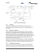
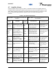
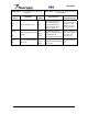

Table Of Contents

044-05117
Chapter 3 Operating Instructions
3-1 Introduction
This chapter contains a description of the G3L-850-135 Multi-Carrier Power Amplifier (MCPA)
controls, indicators, and initial start-up and operating procedures.
3-2 Controls and Indicators
The controls and indicators for the G3L-850-135 Power Amplifier consist of the primary power
RESET toggle switch, the LED STATUS indicator, and the RJ-11 PC Interface as shown in
Figure 3-1.
3-2.1 RESET Switch
The RESET Switch, located on the front panel, has three positions, each with its own function.
• The momentary up position resets fault indications and returns the Amplifier to normal
operation if a critical or hard fault does not prevent such operation. When the switch is
released, it automatically returns to the middle position.
• The middle position allows normal operation. If no critical faults are present, the Amplifier
operates normally.
• The down position is used to turn the amplifier off. The Amplifier remains disabled until the
switch is manually returned to the middle position.
RJ-11 PC
Interface
Multi-Colored LED
Status Indicator
Reset/On/Off
Toggle Switch
Figure 3-1. G3L-850-135 Controls and Indicators
3-2.2 LED Status Indicator and RESET/On/Off Toggle Switch
The status indicator, located on the front panel, is a single, tri-color LED. Status is indicated by a
combination of color and intermittent/steady operation. The LED has tri-color capability: red,
yellow, and green. The LED’s blinking frequency is 0.5-1 Hz with a duty cycle of 45-55%. The
LED indicates the status of the MCPA as listed in Table 3-1.
Installation and Service Manual - G3L-850-135 Multi-Carrier Power Amplifier 3-1